Thank you for understanding what I am trying to do. Doing a bit more searching I see you have helped a number of people with DS18B20 in the past.
I also see there have been some queries about which version of the OneWire library has been used. I can't remember where I got mine from but I see the .h and .cpp files are dated 01/11/2011 10:52. I wondered if this might be one problem area, so I downloaded the latest version (2.2) from github dated 15/3/2018
Sadly this brought no change in the running of my:
Here is the start of my earlier OneWire.cpp file ...
/*
Copyright (c) 2007, Jim Studt  (original old version - many contributors since)

The latest version of this library may be found at:
  http://www.pjrc.com/teensy/td_libs_OneWire.html

Version 2.1:
  Arduino 1.0 compatibility, Paul Stoffregen
  Improve temperature example, Paul Stoffregen
  DS250x_PROM example, Guillermo Lovato
  PIC32 (chipKit) compatibility, Jason Dangel, dangel.jason AT gmail.com
  Improvements from Glenn Trewitt:
  - crc16() now works
  - check_crc16() does all of calculation/checking work.
  - Added read_bytes() and write_bytes(), to reduce tedious loops.
  - Added ds2408 example.
  Delete very old, out-of-date readme file (info is here)


etc...
I have connected 7xDS18B20 in parallel (on breadboard) with NANO and 2.2k pull-up resistor+5V supply. All are working fine. I have attached Temperature Log File, Sketch, and OneWire.h Library.
Sketch:
//12-bit default resolution; external power supply
#include<OneWire.h>
OneWire ds(10);    //Signal in is DPin-10.

//--declare arrays to hold addresses of the sensors
byte ds1Add[8];         //to hold 64-bit ROM Codes/Address of DS1
byte ds2Add[8];
byte ds3Add[8];         //to hold 64-bit ROM Codes/Address of DS1
byte ds4Add[8];
byte ds5Add[8];         //to hold 64-bit ROM Codes/Address of DS1
byte ds6Add[8];
byte ds7Add[8];

//--declare arrays to hold scratchpad (Temp) data of the sensors
byte ds1Temp[9];
byte ds2Temp[9];
byte ds3Temp[9];
byte ds4Temp[9];
byte ds5Temp[9];
byte ds6Temp[9];
byte ds7Temp[9];

float dsTempC;
byte x;

void setup()
{
  Serial.begin(9600);

  //--reset all addresses at the same time----
  ds.reset();

  //-collect addresses of the sensors----
  ds.search(ds1Add);
  ds.search(ds2Add);
  ds.search(ds3Add);
  ds.search(ds4Add);
  ds.search(ds5Add);
  ds.search(ds6Add);
  ds.search(ds7Add);
}

void loop()
{
  DST(ds1Add, ds1Temp);
  Serial.print("DS1 Temp in deg C = "); Serial.print(dsTempC); //show Temp in deg C for DS1
  showAddress(ds1Add);

  DST(ds2Add, ds2Temp);
  Serial.print("DS2 Temp in deg C = "); Serial.print(dsTempC);
  showAddress(ds2Add);

  DST(ds3Add, ds3Temp);
  Serial.print("DS3 Temp in deg C = "); Serial.print(dsTempC);
  showAddress(ds3Add);

  DST(ds4Add, ds4Temp);
  Serial.print("DS4 Temp in deg C = "); Serial.print(dsTempC);
  showAddress(ds4Add);

  DST(ds5Add, ds5Temp);
  Serial.print("DS5 Temp in deg C = "); Serial.print(dsTempC);
  showAddress(ds5Add);

  DST(ds6Add, ds6Temp);
  Serial.print("DS6 Temp in deg C = "); Serial.print(dsTempC);
  showAddress(ds6Add);

  DST(ds7Add, ds7Temp);
  Serial.print("DS7 Temp in deg C = "); Serial.print(dsTempC);
  showAddress(ds7Add);

  Serial.println();
}

void DST(byte *dsAdd, byte *dsTemp)
{
  //--start conversion, wait for conversion, and acquire data --
  ds.reset();
  ds.select(dsAdd);
  ds.write(0x44);
  delay(1000);
  //-----------
  ds.reset();
  ds.select(dsAdd);
  ds.write(0xBE);
  ds.read_bytes(dsTemp, 9);

  //--compute tempC (Temperaure in degree C)----------
  unsigned int dsRawTemp = (dsTemp[1] << 8) | dsTemp[0];
  dsTempC = (float)dsRawTemp / 16.0; //default 12-bit resolution
}

void showAddress(byte *dsAdd)
{
  Serial.print('\t'); Serial.print("ROMCode/Address: ");
  for (int i = 0; i < 8; i++)
  {
    x = dsAdd[i];
    if (x < 0x10)
    {
      Serial.print("0");
    }
    Serial.print(x, HEX);
  }
  Serial.println();
}
I would like to suggest you check the following in your setup:
Check the sensors individually on breadboard fisrt and observe that it is working and note down the address.
Thanks Golam
Yes, I have been checking each sensor individually, and have been slowly adding them in, and it is always stops at the same number of sensors - wherever they are plugged in.
But I note you are using an external power supply - I will try that.
Not much time today - I must catch up on some work!
Here, in my office., I have difficulty to post picture in-line. Please, see the attachment for my 7xDS18B20 and NANO setup. 5V supply has been taken from the NANO power-port.
I loaded your program (but not the library).
It works well with 4 sensors but when I add a fifth it ceases to recognise any.
The results for 4 of 6 sensors (3 in fixed positions and the 4th in a variable position) are...
DS1 Temp in deg C = 25.50 ROMCode/Address: 28F4A57791110268
DS2 Temp in deg C = 26.50 ROMCode/Address: 282C547791140299
DS3 Temp in deg C = 27.31 ROMCode/Address: 28759477911102FC
DS4 Temp in deg C = 26.25 ROMCode/Address: 28AF9377911102A6
DS1 Temp in deg C = 25.75 ROMCode/Address: 28F4A57791110268
DS2 Temp in deg C = 27.44 ROMCode/Address: 28759477911102FC
DS3 Temp in deg C = 26.25 ROMCode/Address: 283D417791130235
DS4 Temp in deg C = 26.25 ROMCode/Address: 28AF9377911102A6
DS1 Temp in deg C = 25.75 ROMCode/Address: 28F4A57791110268
DS2 Temp in deg C = 27.44 ROMCode/Address: 28759477911102FC
DS3 Temp in deg C = 26.94 ROMCode/Address: 28CD3D779113020B
DS4 Temp in deg C = 26.50 ROMCode/Address: 28AF9377911102A6
The wide variations are because I am handling the sensors and as I am in a hurry I am not giving them time to cool down.
BTW I noticed a little typo in the print section of your code and changed DS5 to DS6
DST(ds6Add, ds6Temp);
Serial.print("DS5 Temp in deg C = "); Serial.print(dsTempC);
Thanks again for your interest. The mystery continues - but not today!
Sorry - was I not clear
I have only 6 sensors.
3 of the sensors stay in the same place and I select the 4th from the other 3.
I do not have the time to select any 4 from 6!
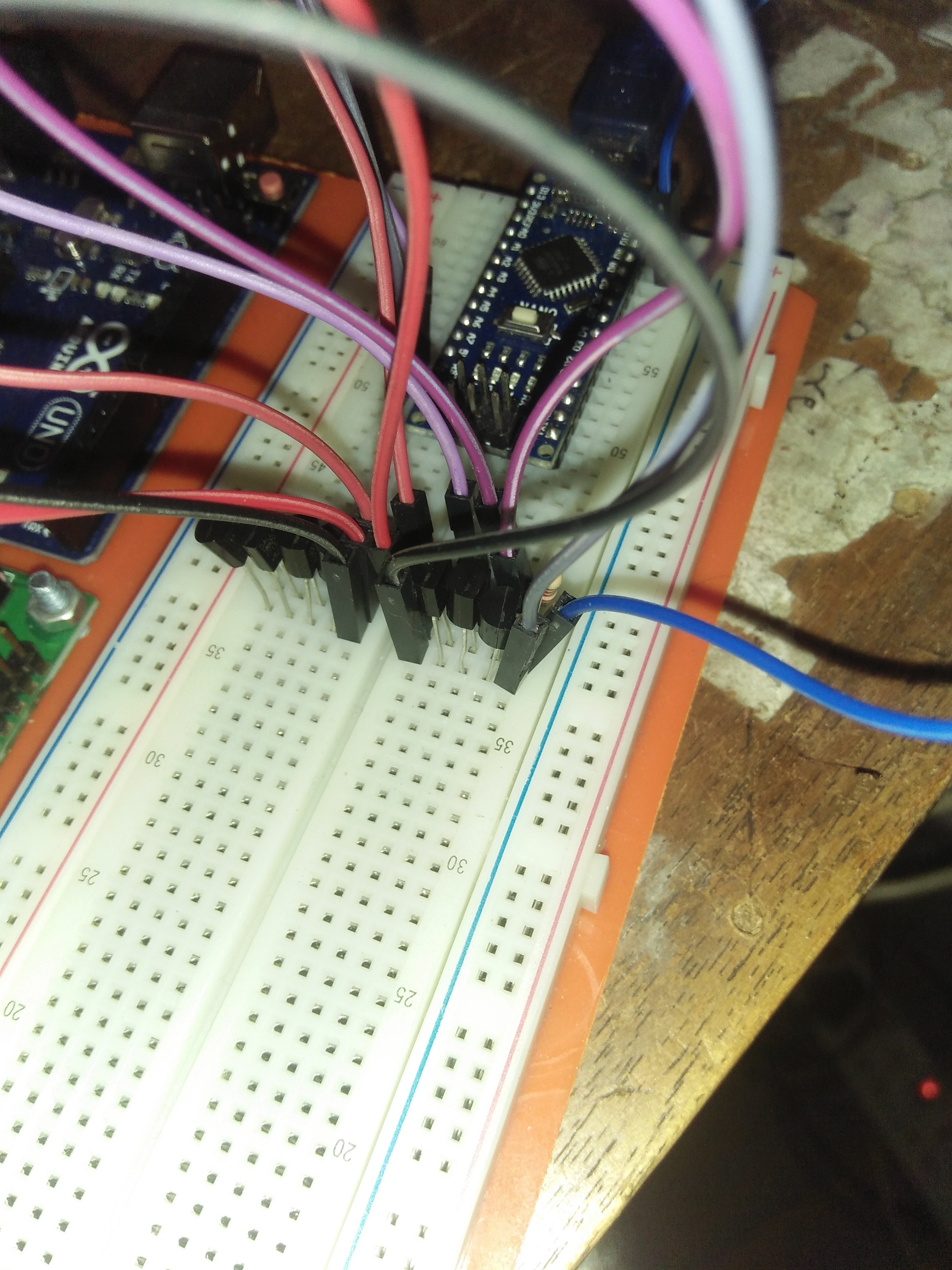
This is my setup for testing 7xDS18B20 sensors simultaneously.
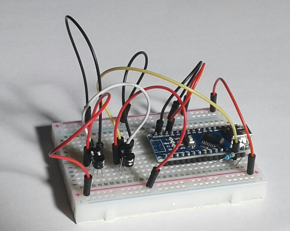
This is your setup:
What are the differences: 1. I have used rectangular-pin jumpers; you have used rounded-pin jumpers which have bad reputation of making either intermittent/high impedance contacts.
2. I have used the pull-up just with the sensor. You have placed it far away from the sensor.
3. I have used minimum jumpers for connection among sensors and NANO; you have used more jumpers. You have made 5V/0V rails, and then you have supplied 5V/0V to the sensors from these rails.
My 7 sensors and @el_supremo 10 sensors are working; your sensors should work?
And if they are still not working, I would solder them together to avoid jumpers and breadboard; they must work at some point?
Ha ha ha!
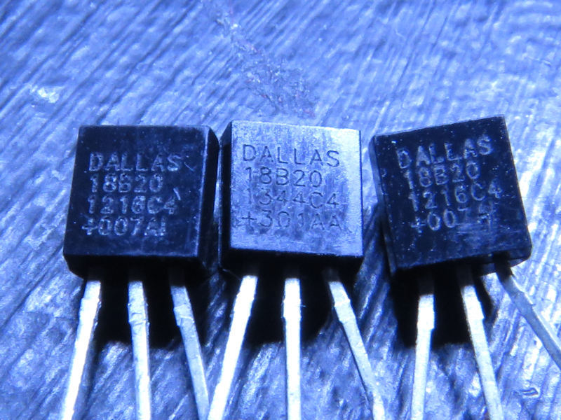
The white is Tippex which I used to identify them - a bit like dominos.
Yes they are DALLAS 18B200
But mine have reference 1813C4 +827AH
I wonder what you think of Golam's comments about my wiring?
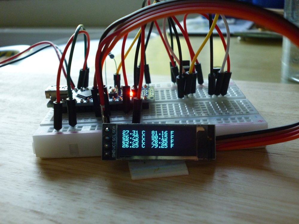
My photo was of an evolving board which I have been runnng with LCD and OLED.
You should see my flying testbed - a Mega packed with loads of sensors and devices to demonstrate what Arduonos can do. A veritable load of spaghetti wiring as it grows organically.
Never had any breadboard problems before
I agree with @GolamMostafa about those jumpers with rounded ends. I had nothing but trouble with them - the pins are a bit small for the holes in the breadboard - and now I only use the square-ended ones shown in my photo.
freddie43:
I wonder what you think of Golam's comments about my wiring?
My comments are only for this particular setup, as it is not working. The aim is to to make your setup working and not to criticize your wiring. In general, your approach of wiring is traditional and fine having had separate rails for the 5V and 0V - that's the way people including I do follow. Kindly, do not misunderstand me.
@el_supremo set up has pull-up far away like your setup, and it has appeared correct as his setup is working. Sometimes, we place it (like the decoupling capacitor placed just near the Vcc pin of the IC) just near the sensor pin to minimize signal reflection.
A big THANK YOU to Pete and Golam (from opposite sides of the globe), for their kindness, understanding and being prepared to experiment and go that extra mile and spend their time trying to help me get to the bottom of my problem.
I have enjoyed the last 2.5 years experimenting with a great range of sensors and devices on my Arduinos, and this Forum has been a great place to search for answers. But this is the first time I have actually sought help - and help came in a big way!
I attach a photo of my OLED display of four DS18B20 sensors - which is about as far as I propose to go at the moment. I can see that my original idea of wiring the house up with a load of sensors in parasite mode is fraught with problems like distance and noise. But that can wait.
Despite all the enjoyment I have had experimenting with my Arduinos, the only really practical application has been making a radio controlled robot car for my grandson, with roll, pitch and yaw controlled by a handheld accelerometer. But although he has great fun with it and has become quite expert as he charges round the garden, of course he would rather have knobs and buttons he could twiddle with - oh, how he does loved twidding!
In closing I have to say something about the rude and unhelpful attitudes of some 'experts' on the Forum
Over the years I have seen that there is a small but hard core of critical people who are negative, don't understand the problems, demand objectives, have no idea why anyone would want to do something, speak of 'nonsense', 'utterly pointless exercises' and treat others as 'dumb' and 'idiots'.
I think the Forum would do well to adopt Instructables' policy:
"We have a be nice policy. Please be positive and constructive"