The decoders have been tested for the Arduino Giga and Due. The decoders are read and processed via interrupt. Usually edge detection is used for the interrupt routine, but I use a system of fixed sampling time that simultaneously processes all encoders. You can choose the sampling period according to the expected max encoder speed. You can start from the max motor speed and the number of pulses per revolution of the encoder. I use a lot of Fischertechnik motors and they have an unload speed of max 600 tr/min. If you have an encoder of 100 pulses per revolution then you have 600/60*100 = 1000 pulses /sec.
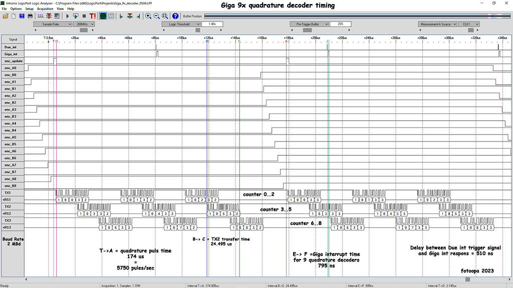
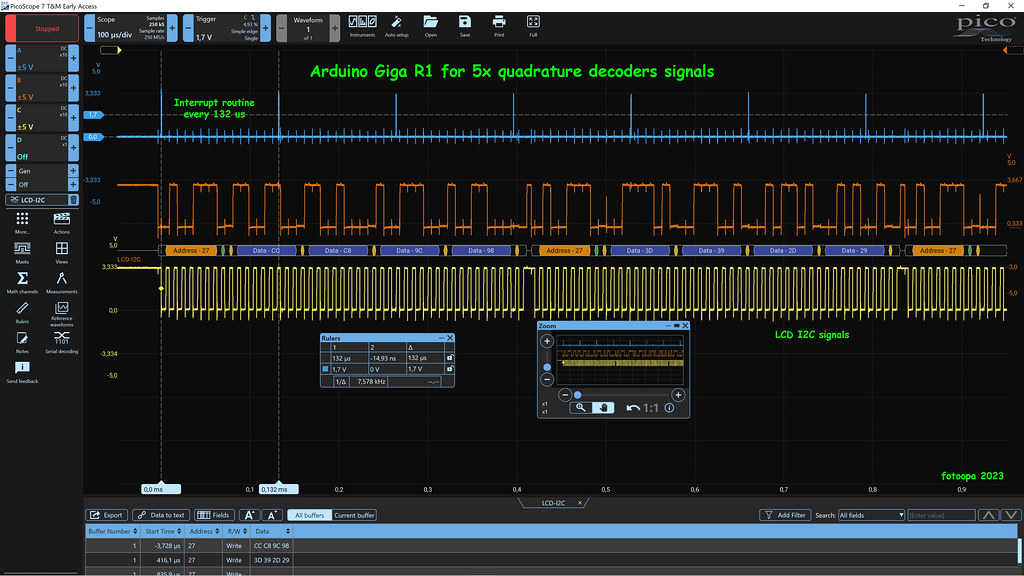
You should also keep in mind that most encoders have a worst-case ratio of 40/60 ratio, so calculate 20% higher speed. I take another 100% safety myself which means I have to make the calculation at 240%, so 2.4Khz instead of 1Khz. It follows that you have to take an interrupt sample at least every 416 us and calculate all encoder positions. I measured the interrupt routine to handle 5 quadrature decoders which is 4691 ns for the Due and 420.5 ns for the Giga. So the Giga is 12x faster. For all tests, I brought the sampling period at 132 us. That's still a lot higher than necessary.
I use an LCD 4x20 char display with I2C. I read that 10x per sec to display position values.
You can see a scope shot here:
 Giga_5x_decoder_scope_0428 by Frans, on Flickr
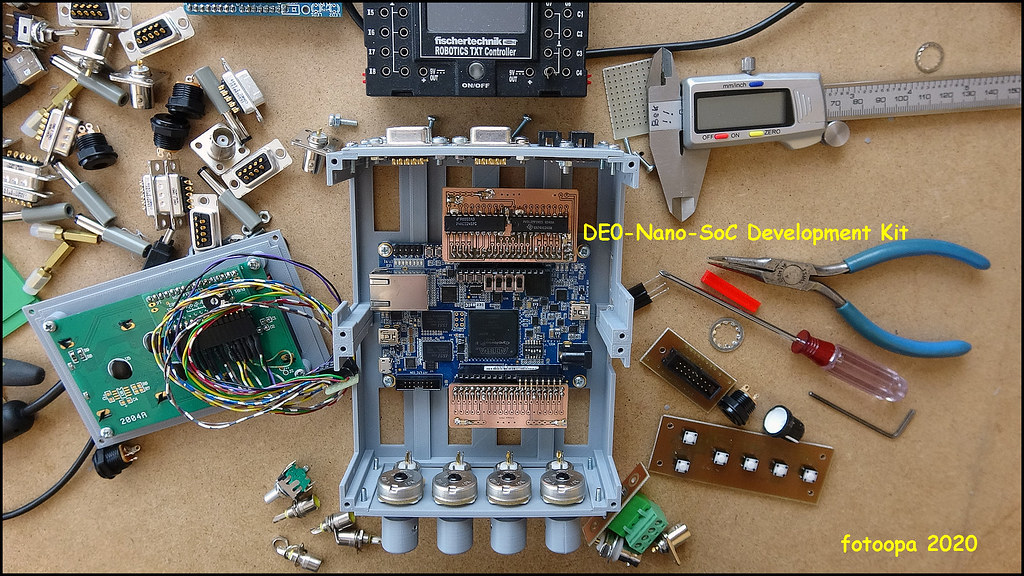
The Giga setup:
 Giga_5x_decoder_20230428 by Frans, on Flickr
And the Due setup:
 Due_decoders_20230427_152454 by Frans, on Flickr
The Due program:
/*
Multiple Quadrature decoders + LCD display 4x20 char
fotoopa 2023
https://www.flickr.com/photos/fotoopa_hs/

The Giga takes about  416 ns to process all 5 decoders in the interrupt routine
The Due  takes about 4691 ns to process all 5 decoders in the interrupt routine
The Giga is about 12x faster than the Due.
Interrupt every 132 us via timer

*/
#include "HD44780_LCD_PCF8574.h"
HD44780LCD myLCD( 4, 20, 0x27); // I2C LCD adr $27 4x20 char

static int32_t counter0 = 100;  // powerup counter value 100
static int32_t counter1 = 200;  // powerup counter value 200
static int32_t counter2 = 300;  // powerup counter value 300
static int32_t counter3 = 400;  // powerup counter value 400
static int32_t counter4 = 500;  // powerup counter value 500

static uint16_t enc_inputs = 0;

bool ena_ena0;
bool ena_dir0;
bool ena_ena1;
bool ena_dir1;
bool ena_ena2;
bool ena_dir2;
bool ena_ena3;
bool ena_dir3;
bool ena_ena4;
bool ena_dir4;
bool ena_ena5;
bool ena_dir5;
bool enc_A0;
bool enc_B0;
bool enc_A1;
bool enc_B1;
bool enc_A2;
bool enc_B2;
bool enc_A3;
bool enc_B3;
bool enc_A4;
bool enc_B4;
bool enc_A5;
bool enc_B5;
bool enc_old_A0;
bool enc_old_B0;
bool enc_old_A1;
bool enc_old_B1;
bool enc_old_A2;
bool enc_old_B2;
bool enc_old_A3;
bool enc_old_B3;
bool enc_old_A4;
bool enc_old_B4;

void setup() {
  Serial.begin(115200);
  pinMode(33, OUTPUT);    // D33 pulse output for trigger scope timing
  /*
  Clearing one (or more) PIO line(s) and setting another one (or more) PIO line(s) synchronously cannot be done by
  using PIO_SODR and PIO_CODR registers. It requires two successive write operations into two different
  registers. To overcome this, the PIO Controller offers a direct control of PIO outputs by single write access to
  PIO_ODSR (Output Data Status Register).Only bits unmasked by PIO_OWSR (Output Write Status Register) are
  written. The mask bits in PIO_OWSR are set by writing to PIO_OWER (Output Write Enable Register) and cleared
  by writing to PIO_OWDR (Output Write Disable Register).
  After reset, the synchronous data output is disabled on all the I/O lines as PIO_OWSR resets at 0x0.
  */
  PIOC -> PIO_OWSR = PIO_OWSR_P1; // Output Write Status Register actief for pin D33 = scope trigger pulse

  digitalWrite(33, 0);
  pinMode(25, INPUT);   // PIOD bit 0 D25
  pinMode(26, INPUT);   // PIOD bit 1 D26
  pinMode(27, INPUT);   // PIOD bit 2 D27
  pinMode(28, INPUT);   // PIOD bit 3 D28
  pinMode(14, INPUT);   // PIOD bit 4 D14
  pinMode(15, INPUT);   // PIOD bit 5 D15
  pinMode(29, INPUT);   // PIOD bit 6 D29
  pinMode(11, INPUT);   // PIOD bit 7 D11
  pinMode(12, INPUT);   // PIOD bit 8 D12
  pinMode(30, INPUT);   // PIOD bit 9 D30

  PIOD->PIO_PUER = PIO_PUDR_P0 |PIO_PUDR_P1 |PIO_PUDR_P2 |PIO_PUDR_P3
                  |PIO_PUDR_P4 |PIO_PUDR_P5 |PIO_PUDR_P6 |PIO_PUDR_P7
                  |PIO_PUDR_P8 |PIO_PUDR_P9 ;  // pullup on inputs for D25 D26 D27 D28 D14 D15 D29 D11 D12 D30
  tc_setup();
  delay(5);
  myLCD.PCF8574_LCDInit(LCDCursorTypeOff);
  myLCD.PCF8574_LCDClearScreen();
  myLCD.PCF8574_LCDBackLightSet(true);
}

void loop() {
  char titel[] = " Quadrature Decoders";
  myLCD.PCF8574_LCDGOTO(LCDLineNumberOne, 0);
  myLCD.PCF8574_LCDSendString(titel);

  while (true) {
	  myLCD.PCF8574_LCDGOTO(LCDLineNumberTwo, 9);
	  myLCD.print(counter0);
    myLCD.PCF8574_LCDSendChar(' ');
	  myLCD.PCF8574_LCDGOTO(LCDLineNumberThree, 4);
	  myLCD.print(counter1);
    myLCD.PCF8574_LCDSendChar(' ');
	  myLCD.PCF8574_LCDGOTO(LCDLineNumberFour, 4);
	  myLCD.print(counter2);
    myLCD.PCF8574_LCDSendChar(' ');
	  myLCD.PCF8574_LCDGOTO(LCDLineNumberThree, 14);
	  myLCD.print(counter3);
    myLCD.PCF8574_LCDSendChar(' ');
	  myLCD.PCF8574_LCDGOTO(LCDLineNumberFour, 14);
	  myLCD.print(counter4);
    myLCD.PCF8574_LCDSendChar(' ');
    delay(100);
  }
}

void tc_setup() {
  PMC->PMC_PCER1 |= PMC_PCER1_PID35;                        // TC8 power ON : Timer Counter 2 channel 2 IS TC8 - see page 38
  TC2->TC_CHANNEL[2].TC_CMR = TC_CMR_TCCLKS_TIMER_CLOCK2    // MCK/8 = 82/8 --> 10.5 M Hz, clk on rising edge
                              | TC_CMR_WAVE                 // Waveform mode
                              | TC_CMR_WAVSEL_UP_RC;        // UP mode with automatic trigger on RC Compare
  TC2->TC_CHANNEL[2].TC_RC = 42;                            // 4 usec/ timerloop
  TC2->TC_CHANNEL[2].TC_IER = TC_IER_CPCS;                  // Interrupt on RC compare match
  TC2->TC_CHANNEL[2].TC_CCR = TC_CCR_SWTRG | TC_CCR_CLKEN;  // Software trigger TC2 counter and enable
  NVIC_EnableIRQ(TC8_IRQn);
}
static uint32_t Count;
void TC8_Handler() {

  if (Count++ == 31) {                // TC_CMR_TCCLKS_TIMER_CLOCK2 x32 = 128 us decoder update periode.
  Count = 0;                          // update duration to process all 5 decoders 4.775 us
  PIOC -> PIO_SODR = PIO_SODR_P1 ;    // set pin D33 high scope trigger pulse
  // copy encoders old
  enc_old_A0 = enc_A0;
  enc_old_B0 = enc_B0;
  enc_old_A1 = enc_A1;
  enc_old_B1 = enc_B1;
  enc_old_A2 = enc_A2;
  enc_old_B2 = enc_B2;
  enc_old_A3 = enc_A3;
  enc_old_B3 = enc_B3;
  enc_old_A4 = enc_A4;
  enc_old_B4 = enc_B4;
  enc_inputs  = (PIOD->PIO_PDSR);   // Read PIOD Reg  for Data: D25 D26 D27 D28 D14 D15 D29 D11 D12 D30 (D32)
  // copy encoders
  enc_A0 = enc_inputs & PIO_PER_P0; // copy D25 level
  enc_B0 = enc_inputs & PIO_PER_P1; // copy D26 level
  enc_A1 = enc_inputs & PIO_PER_P2; // copy D27 level
  enc_B1 = enc_inputs & PIO_PER_P3; // copy D28 level
  enc_A2 = enc_inputs & PIO_PER_P4; // copy D14 level
  enc_B2 = enc_inputs & PIO_PER_P5; // copy D15 level
  enc_A3 = enc_inputs & PIO_PER_P6; // copy D29 level
  enc_B3 = enc_inputs & PIO_PER_P7; // copy D11 level
  enc_A4 = enc_inputs & PIO_PER_P8; // copy D12 level
  enc_B4 = enc_inputs & PIO_PER_P9; // copy D30 level
  // ena dir
  ena_ena0 = enc_A0 ^ enc_old_A0 ^ enc_B0 ^ enc_old_B0;
  ena_dir0 = enc_A0 ^ enc_old_B0;
  ena_ena1 = enc_A1 ^ enc_old_A1 ^ enc_B1 ^ enc_old_B1;
  ena_dir1 = enc_A1 ^ enc_old_B1;
  ena_ena2 = enc_A2 ^ enc_old_A2 ^ enc_B2 ^ enc_old_B2;
  ena_dir2 = enc_A2 ^ enc_old_B2;
  ena_ena3 = enc_A3 ^ enc_old_A3 ^ enc_B3 ^ enc_old_B3;
  ena_dir3 = enc_A3 ^ enc_old_B3;
  ena_ena4 = enc_A4 ^ enc_old_A4 ^ enc_B4 ^ enc_old_B4;
  ena_dir4 = enc_A4 ^ enc_old_B4;
  // pos direction
  if (ena_ena0 & ena_dir0) counter0++;
  if (ena_ena1 & ena_dir1) counter1++;
  if (ena_ena2 & ena_dir2) counter2++;
  if (ena_ena3 & ena_dir3) counter3++;
  if (ena_ena4 & ena_dir4) counter4++;
  // negatief direction
  if (ena_ena0 & !ena_dir0) counter0--;
  if (ena_ena1 & !ena_dir1) counter1--;
  if (ena_ena2 & !ena_dir2) counter2--;
  if (ena_ena3 & !ena_dir3) counter3--;
  if (ena_ena4 & !ena_dir4) counter4--;
  PIOC -> PIO_CODR = PIO_CODR_P1 ;      // set pin D33 low scope trigger pulse.
}
TC2->TC_CHANNEL[2].TC_SR;               // Read and clear status register
}
And the Giga program:
/*
Multiple Quadrature decoders + LCD display 4x20 char
fotoopa 2023
https://www.flickr.com/photos/fotoopa_hs/

The Giga takes about  416 ns to process all 5 decoders in the interrupt routine
The Due  takes about 4691 ns to process all 5 decoders in the interrupt routine
The Giga is about 12x faster than the Due.
Interrupt every 132 us via pin 2, signal given by the Arduino Due.
*/

#include "HD44780_LCD_PCF8574.h"
HD44780LCD myLCD( 4, 20, 0x27); // I2C LCD adr $27 4x20 char

static int counter0 = 200;
static int counter1 = 300;
static int counter2 = 400;
static int counter3 = 500;
static int counter4 = 600;
static uint16_t enc_inputs = 0;

bool ena_ena0;
bool ena_dir0;
bool ena_ena1;
bool ena_dir1;
bool ena_ena2;
bool ena_dir2;
bool ena_ena3;
bool ena_dir3;
bool ena_ena4;
bool ena_dir4;
bool ena_ena5;
bool ena_dir5;
bool enc_A0;
bool enc_B0;
bool enc_A1;
bool enc_B1;
bool enc_A2;
bool enc_B2;
bool enc_A3;
bool enc_B3;
bool enc_A4;
bool enc_B4;
bool enc_A5;
bool enc_B5;
bool enc_old_A0;
bool enc_old_B0;
bool enc_old_A1;
bool enc_old_B1;
bool enc_old_A2;
bool enc_old_B2;
bool enc_old_A3;
bool enc_old_B3;
bool enc_old_A4;
bool enc_old_B4;
/*
GPIOJ  0  D25           enc_A0 = enc_inputs & 0x01;
GPIOJ  1  D27           enc_B0 = enc_inputs & 0x02;
GPIOJ  2  D29           enc_A1 = enc_inputs & 0x04;
GPIOJ  3  D31           enc_B1 = enc_inputs & 0x08;
GPIOJ  4  D33           enc_A2 = enc_inputs & 0x10;
GPIOJ  5  D35           enc_B2 = enc_inputs & 0x20;
GPIOJ  6  D37           enc_A3 = enc_inputs & 0x40;
GPIOJ  7  D38           enc_B3 = enc_inputs & 0x80;
GPIOJ  8  D4            ----
GPIOJ  9  D57	XCLK Cam  ----
GPIOJ 10  D11	SPI5_COPI ----
GPIOJ 11  D12	SPI5_CIPO ----
GPIOJ 12  D22           Scope trigger ouput
GPIOJ 13  D87	Green led ----
GPIOJ 14  D26           enc_A4 = enc_inputs & 0x4000;
GPIOJ 15  D28           enc_B4 = enc_inputs & 0x8000;
*/
#define PIN_int_decoder 2    //interrupt request pin 2

void setup() {
  Serial.begin(115200);
  pinMode(D22, OUTPUT);    // scope trigger signal
  digitalWrite(D22, 0);    // trigger scope low
  pinMode(D25, INPUT);     // enc_A0
  pinMode(D27, INPUT);     // enc_B0
  pinMode(D29, INPUT);     // enc_A1
  pinMode(D31, INPUT);     // enc_B1
  pinMode(D33, INPUT);     // enc_A2
  pinMode(D35, INPUT);     // enc_B2
  pinMode(D37, INPUT);     // enc_A3
  pinMode(D38, INPUT);     // enc_B3
  pinMode(D26, INPUT);     // enc_A4
  pinMode(D28, INPUT);     // enc_B3
  // set pullup registers  GPIOJ -> PUPDR = 1<<30 | 1<<28 | 1<<14 | 1<<12 | 1<<10 | 1<<8 || 1<<6  | 1<<4  | 1<<2  | 1<<0 ;
  GPIOJ -> PUPDR =  GPIO_PUPDR_PUPD15_0 |
                    GPIO_PUPDR_PUPD14_0 |
                    GPIO_PUPDR_PUPD7_0 |
                    GPIO_PUPDR_PUPD6_0 |
                    GPIO_PUPDR_PUPD5_0 |
                    GPIO_PUPDR_PUPD4_0 |
                    GPIO_PUPDR_PUPD3_0 |
                    GPIO_PUPDR_PUPD2_0 |
                    GPIO_PUPDR_PUPD1_0 |
                    GPIO_PUPDR_PUPD0_0 ; // set pullup register for all decoder lines.
  pinMode(PIN_int_decoder, INPUT);
  attachInterrupt(digitalPinToInterrupt(PIN_int_decoder), Int_Decoder_Handler, RISING);
  delay(5);
  myLCD.PCF8574_LCDInit(LCDCursorTypeOff);
  myLCD.PCF8574_LCDClearScreen();
  myLCD.PCF8574_LCDBackLightSet(true);
}

void loop() {
  char titel[] = " Quadrature Decoders";
  myLCD.PCF8574_LCDGOTO(LCDLineNumberOne, 0);
  myLCD.PCF8574_LCDSendString(titel);
  while (true) {
    delay(100);     // Update LCD counters every 100 ms
    update_lcd();
  }
}

void update_lcd()   // Update the 5 counters on the LCD
{
  	myLCD.PCF8574_LCDGOTO(LCDLineNumberTwo, 9);
	  myLCD.print(counter0);
    myLCD.PCF8574_LCDSendChar(' ');
	  myLCD.PCF8574_LCDGOTO(LCDLineNumberThree, 4);
	  myLCD.print(counter1);
    myLCD.PCF8574_LCDSendChar(' ');
	  myLCD.PCF8574_LCDGOTO(LCDLineNumberFour, 4);
	  myLCD.print(counter2);
    myLCD.PCF8574_LCDSendChar(' ');
	  myLCD.PCF8574_LCDGOTO(LCDLineNumberThree, 14);
	  myLCD.print(counter3);
    myLCD.PCF8574_LCDSendChar(' ');
	  myLCD.PCF8574_LCDGOTO(LCDLineNumberFour, 14);
	  myLCD.print(counter4);
    myLCD.PCF8574_LCDSendChar(' ');
}

void Int_Decoder_Handler() {
  // set pin D22 high. Processing time interrupt routine 461 ns
  // Interrupt every 132 us via pin 2, signal given by the Arduino Due.
  GPIOJ -> BSRR = GPIO_BSRR_BS12_Msk;
  // copy encoders old
  enc_old_A0 = enc_A0;
  enc_old_B0 = enc_B0;
  enc_old_A1 = enc_A1;
  enc_old_B1 = enc_B1;
  enc_old_A2 = enc_A2;
  enc_old_B2 = enc_B2;
  enc_old_A3 = enc_A3;
  enc_old_B3 = enc_B3;
  enc_old_A4 = enc_A4;
  enc_old_B4 = enc_B4;
  // read all pins on input data register port GPIOJ
  enc_inputs  = (GPIOJ->IDR);
  // copy encoders
  enc_A0 = enc_inputs & 0x01;
  enc_B0 = enc_inputs & 0x02;
  enc_A1 = enc_inputs & 0x04;
  enc_B1 = enc_inputs & 0x08;
  enc_A2 = enc_inputs & 0x10;
  enc_B2 = enc_inputs & 0x20;
  enc_A3 = enc_inputs & 0x40;
  enc_B3 = enc_inputs & 0x80;
  enc_A4 = enc_inputs & 0x4000;
  enc_B4 = enc_inputs & 0x8000;
  // ena dir
  ena_ena0 = enc_A0 ^ enc_old_A0 ^ enc_B0 ^ enc_old_B0;
  ena_dir0 = enc_A0 ^ enc_old_B0;
  ena_ena1 = enc_A1 ^ enc_old_A1 ^ enc_B1 ^ enc_old_B1;
  ena_dir1 = enc_A1 ^ enc_old_B1;
  ena_ena2 = enc_A2 ^ enc_old_A2 ^ enc_B2 ^ enc_old_B2;
  ena_dir2 = enc_A2 ^ enc_old_B2;
  ena_ena3 = enc_A3 ^ enc_old_A3 ^ enc_B3 ^ enc_old_B3;
  ena_dir3 = enc_A3 ^ enc_old_B3;
  ena_ena4 = enc_A4 ^ enc_old_A4 ^ enc_B4 ^ enc_old_B4;
  ena_dir4 = enc_A4 ^ enc_old_B4;
  // pos direction
  if (ena_ena0 & ena_dir0) counter0++;
  if (ena_ena1 & ena_dir1) counter1++;
  if (ena_ena2 & ena_dir2) counter2++;
  if (ena_ena3 & ena_dir3) counter3++;
  if (ena_ena4 & ena_dir4) counter4++;
  // negatief direction
  if (ena_ena0 & !ena_dir0) counter0--;
  if (ena_ena1 & !ena_dir1) counter1--;
  if (ena_ena2 & !ena_dir2) counter2--;
  if (ena_ena3 & !ena_dir3) counter3--;
  if (ena_ena4 & !ena_dir4) counter4--;
  GPIOJ -> BSRR = GPIO_BSRR_BR12_Msk;     // set pin D22 low
  }
Now I have a problem using a timer interrupt at the Giga. I cannot find a solution to trigger a timer like with the Due. There are also no examples to be found after many searches. Probably there are no sources for this yet. I would be greatly helped if someone could help me for this to trigger an interrupt from a timer.
Now I do it via:
attachInterrupt(digitalPinToInterrupt(PIN_int_decoder), Int_Decoder_Handler, RISING);
I post all my photos of setups and measurements on Flickr, most in UHD resolution. You can find the link in my program at the top.
I have now made the tests for 5 decoders but more decoders would not give much higher load. I did choose the inputs so that they are on 1 port. This makes the processing faster.
Frans.