That should do it! Adafruit makes good stuff. And good docs and support.
If the device ran fine with enable HIGH, the multiplexer should take care of that.
Instead of manipulating the enable lines, you'll be redirecting the multiplexer. Not much different. Just transport. Not protocol.
Can you point me in the direction of how to do that.
This is my attempt.
#include <DFRobot_B_LUX_V30B.h>
#include <Wire.h>


#define TCAADDR 0x70
DFRobot_B_LUX_V30B    myLux(13);//The sensor chip is set to 13 pins, SCL and SDA adopt default configuration


void tcaselect(uint8_t i) {
  if (i > 7) return;

  Wire.beginTransmission(TCAADDR);
  Wire.write(1 << i);
  Wire.endTransmission();
}


void setup(void)
{
  Serial.begin(9600);
  Serial.println("SEN0390 TEST"); Serial.println("");

  /* Initialise the 1st sensor */
  tcaselect(0);
  myLux.begin();


  /* Initialise the 2nd sensor */
  tcaselect(6);
  myLux.begin();

  }


void loop(void)
{

  tcaselect(0);

  Serial.print("value: ");
  Serial.print(myLux.lightStrengthLux());
  Serial.println(" (lux).");
  delay(1000);

  tcaselect(7);
  Serial.print("value: ");
  Serial.print(myLux.lightStrengthLux());
  Serial.println(" (lux).");
  delay(1000);

  delay(500);
}
If you plan on using the multiplexer, you need the library for it. The PCA9548 uses the same library. Download the zip. Open the IDE and use
Sketch -> Include library -> Add zip library.
It imports good examples. I've dealt with Rob Tillaart before. Nice guy.
As you already know from the DFRobot wiki page:
This sensor is sealed by software IIC, and can not be used with other equipment or sensors using hardware IIC.
So you can forget about the I2C MUX.
However, you can use two 74HC4051 analog multiplexers, one for SCL and one for SDA.
So besides pins for SCL and SDA, you will need 3 more pins to control the 4051.
Do you have 3 pins avaliable?
If you need a wiring diagram just let me know.
It apparently is working on hardware i2c, just not multiple units using the enable lines.
The multiplexer should take care of that.
Shame the enable lines take the SDA and SCL lines LOW.
Hi Jim-p
I have two 74HC4051 and waiting on delivery.
Do I just use the same pins for switch both multiplexers?

Why it needs be analog to switch a digital pins?
If you have a solution, I'm sure @anders_ringgaard would like to see it.
@jim-p
It is not as a dispute, just a question...
It's not the analog part. It's the bidirectional part that matters.
I'm waiting for @anders_ringgaard reply
Hi Jim-p.
These are the boards a bought.

Are you suggesting ther is a way to do it with a digital MUX?
I don't know how.
Thanks Jim-p.
I'll let you know how it goes, when I put it together later in the week ![]()
No hurry
Thank you jim-p.
I got it to work ![]()
Have a nice day!
HI jim-p,
Now i have run in to another issue.
I get incorrect data, when I connect the sensors to a long wire.
Could this because I switch to fast bestween them. I have put in a delay between readings, but i dont know if i need a dealy somewhere else?
#include <DFRobot_B_LUX_V30B.h>
DFRobot_B_LUX_V30B    myLux(13);//The sensor chip is set to 13 pins, SCL and SDA adopt default configuration

//Mux control pins
int s0 = 8;
int s1 = 9;
int s2 = 10;
int s3 = 11;

//Mux in "SIG" pin
int SIG_pin = 0;


void setup(){
  pinMode(s0, OUTPUT);
  pinMode(s1, OUTPUT);
  pinMode(s2, OUTPUT);
  pinMode(s3, OUTPUT);

  digitalWrite(s0, LOW);
  digitalWrite(s1, LOW);
  digitalWrite(s2, LOW);
  digitalWrite(s3, LOW);

  Serial.begin(9600);
  myLux.begin();
}


void loop(){

  //Loop through and read all 16 values
  //Reports back Value at channel 6 is: 346
  for(int i = 0; i < 6; i ++){
    Serial.print("Value at channel ");
    Serial.print(i);
    Serial.print("is : ");
    Serial.println(readMux(i));
    delay(1000);
      Serial.print(myLux.lightStrengthLux());
  Serial.println(" (lux).");
    delay(1000);
  }

}


int readMux(int channel){
  int controlPin[] = {s0, s1, s2, s3};

  int muxChannel[16][4]={
    {0,0,0,0}, //channel 0
    {1,0,0,0}, //channel 1
    {0,1,0,0}, //channel 2
    {1,1,0,0}, //channel 3
    {0,0,1,0}, //channel 4
    {1,0,1,0}, //channel 5
    {0,1,1,0}, //channel 6
    {1,1,1,0}, //channel 7
    {0,0,0,1}, //channel 8
    {1,0,0,1}, //channel 9
    {0,1,0,1}, //channel 10
    {1,1,0,1}, //channel 11
    {0,0,1,1}, //channel 12
    {1,0,1,1}, //channel 13
    {0,1,1,1}, //channel 14
    {1,1,1,1}  //channel 15
  };

  //loop through the 4 sig
  for(int i = 0; i < 6; i ++){
    digitalWrite(controlPin[i], muxChannel[channel][i]);
  }

  //read the value at the SIG pin
  int val = analogRead(SIG_pin);
  delay(1000);

  //return the value
  return val;

}
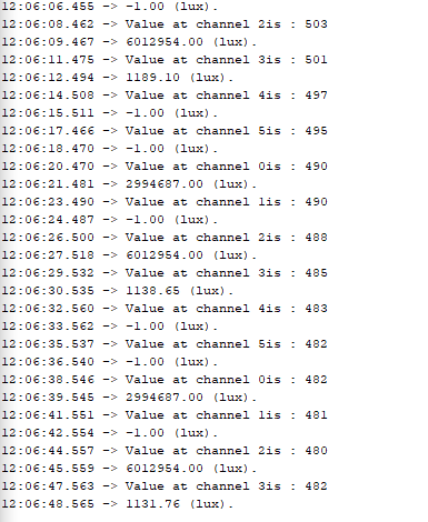
they sometimes read the correct data, just not everytime