I just combined the code for a servo and a DC motor, but I found the dc not working.
I think the code is correct but not 100% sure. can somebody tell me if there are any mistakes in my code? thank you. when I send the values from my android and I can see the values arrive in Arduino. and I also measured the voltage has changed on the Nano board pins. I could not figure it out why the dc motor not working.
I use nano board. HC06 Bluetooth module, L298N motor driver. 12V power supply.
As already told, please post schematics, not a bird nest Fritzing picture. No obvious mistake found in the code so far.
Have You tried using Serial.print inside the code, and serial monitor in the IDE? Print outs like "Start executed", "Stop executed etc. That's a powerful tool for debugging code.
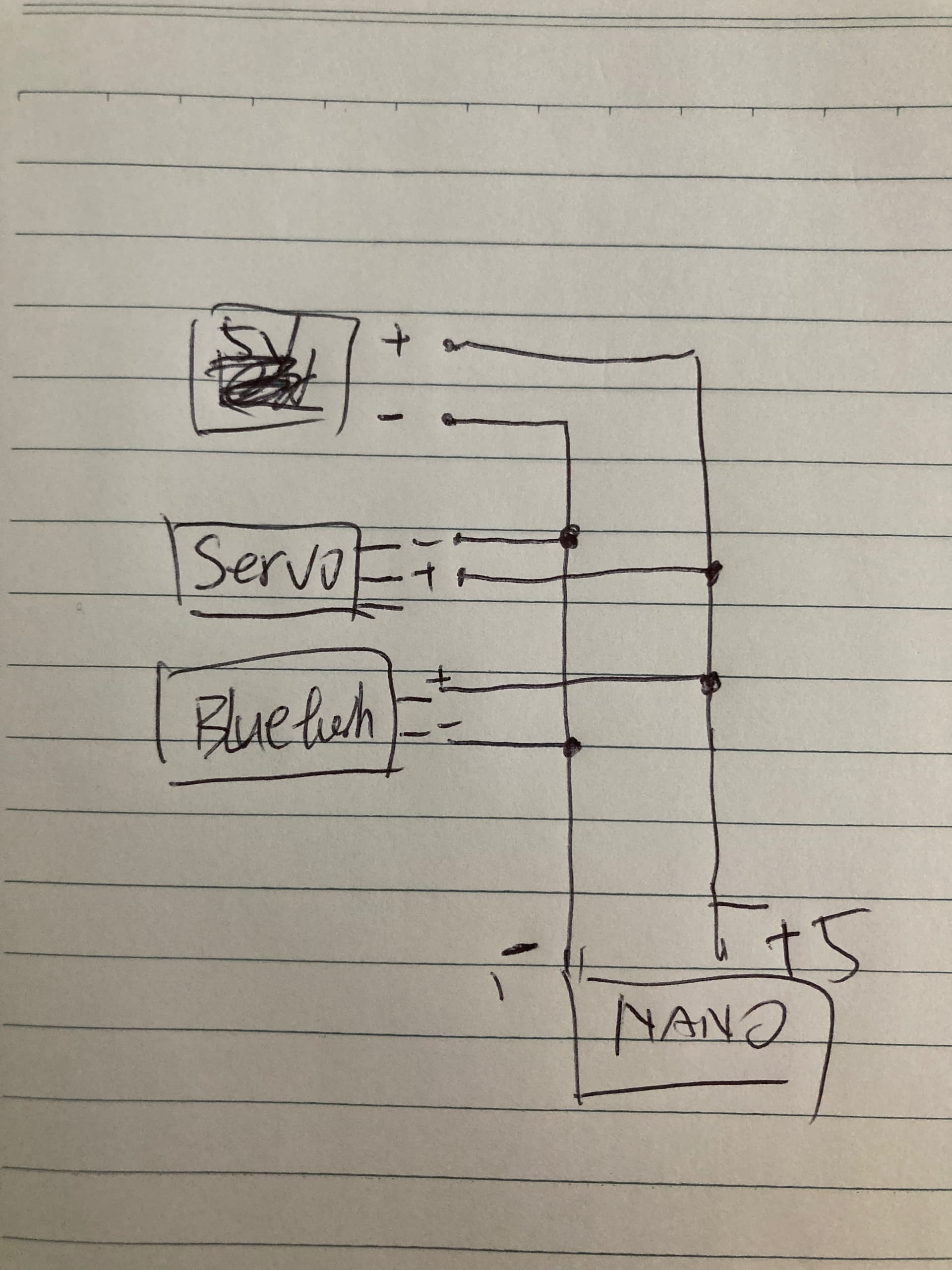
Hi, Rail. I just upload a schematic. and if I just make a code block for Motor, it's working well. but if I combine the servo and motor, the motor will not show any sign of spinning. I double-checked the wirings and all connections are good. also, I check the values in Serial.println() coming correctly. I have no idea what causes the problem. I'm gonna use a mega2560 to try the same code and see if they work or not.
That's not schematics. It's a Fritzing, a colorful birdnest, as useful as a road map without names.
Guesses: The 5 volt converter on the L298 board is overloaded by the servo and the BT circuit. Give the servo and the BT a real power supply. Never use controllers and similar for supplying power.
Do You get thecurrent needed? Check the datasheet for the L298 board regarding the current capacity of that 5 volt converter. I really can't believe it is powerful enough.
That schematics makes no change. It's still the same 5 volt converter.
Mega works.... i find it hard to believe.
Last guess. The Nano pins, timers,.... are different than You think. Improper library used?
for sure, Rail. mega 2560 works perfectly. and I did not use any external power to servo and Bluetooth. I currently disable the code block to servo and the motor still doesn't work. another guess is that the Nano board is fried.
I probably have the answer. There must be a conflict there. I could not use the dc motor and servo at the same time. when I use any one of those devices individually, I get no issues.
That was good news. We can rule out colliding libraries. Then remains: this is a powering problem!
Get hold of one solid 5 volt power capable of some amps, say 5 - 10 amps and feed the dc motor, the servo and BT.
Hrmm. Fine You found a way out of this, but....
Now reading the datasheets for the L298D I say You're out on deep water. The spec says this:
What does the l298n module consist of?
This module consists of an L298 motor driver IC and a 78M05 5V regulator.
The 78M05 supplies 1/2 amp according to its datasheet.
Please note this!
As I said earlier, give the external devices a proper power supply. Running Your setup for long it's a question of time before it will fail.
Thank you so much, Rail! The 78M05 5V regulator offering a half amp may not be enough for a servo and Bluetooth. I could give a better external power supply to them. But there's another reason that I don't want the Nano. The thing you mentioned earlier in the post. It might be an improper Libraries! As I said the code is working on a Mega2560 running smoothly, but Nano. I searched the whole forum and I do find out some clues about the conflict in running several things on a Nano at the same time. there must be a solution, but It takes too long to learn by myself So I think taking the Mega2560 will be a better choice instead of keeping using the Nano.
I've been working with electronics and programming for almost 50 years but only a few years with Arduinos, UNOs. Not much knowledge about the speciallity of the different types of controllers. Forum now and then solves issues where incompatble libraries and controller type was the reason. That's what I've picked in forum.
Yes, go for a more powerful supply of 5 volt. Good choice to use a Mega for the moment.
Good luck!