I have triple-checked the connections and have even dismantled and reconnected everything twice. I have tried seeing other solutions on this forum too, but nothing seems to help.
My soldering of the headpins on the LCD also seems fine.
I have already tried the following:
Disconnecting all data pins connecting only the power pins to get a row of black boxes on the top.
Adjusting the potentiometer.
Connecting both ends of the potentiometer to GND, as suggested by someone on some other forum thread.
Checking if my potentiometer is defective. I disconnected everything and performed an analogRead on the potentiometer(as shown in the code), and the potentiometer correctly varies from 0 to 1023 on turning its wheel.
None of these have helped. Since the lights are turning on, I don't think there's a problem with the LCD either. Can anyone please help me out?
PS: I'm a CS student so all this is a bit new for me
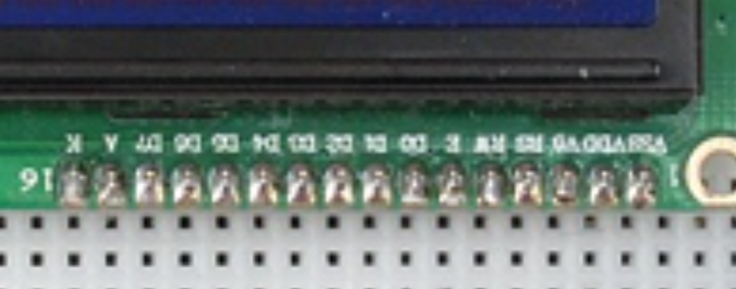
EDIT2: You appear to be missing 4 data lines.
EDIT: OOPS, just noticed you don't have the I2C daughter board.
In that case, I can't remember how to do it the old way.
First I would use the LiquidCrystal_I2C library, that way there is only 2 wires (SDA, SCL) plus power. Also make sure the backlight is jumpered at the back/side and when "Hello World" is supposed to be on the screen, adjust the small pot to adjust the backlight.
Hey, I'm actually following a tutorial from a YouTuber (not any random one, he's a really good youtuber) and I'm doing just as he is and he is the one who designed the circuit he got it right. I didn't see any comments complaining about this issue so it's definitely an issue on my side. I don't have an I2c daughter board, and I don't even want to buy one just yet, I want to learn how stuff goes like this ('the old way' as you mention).
And by adjusting the backlight are you implying that the brightness of the LCD changes when the potentiometer is turned?
Coz that's NOT happening with me. The brightness of the screen is constant throughout the potentiometer's range. Also, I forgot to mention that I also tried putting a resistor on the 15th(BLA) pin in series to the 5V, (as shown in the circuit diagram of the LCD Hello World sample program on Arduino's official website) and doing that reduced the brightness of the 'backlight' meaning that my LCD is capable of doing that too, but isn't doing it for some reason.
In that case, check this guys work. I am a member there and Bill is very good. I think there is a difference in your wiring and Bill's but I am having trouble (autistic 82yo) rotating the diagrams in my head. LINK
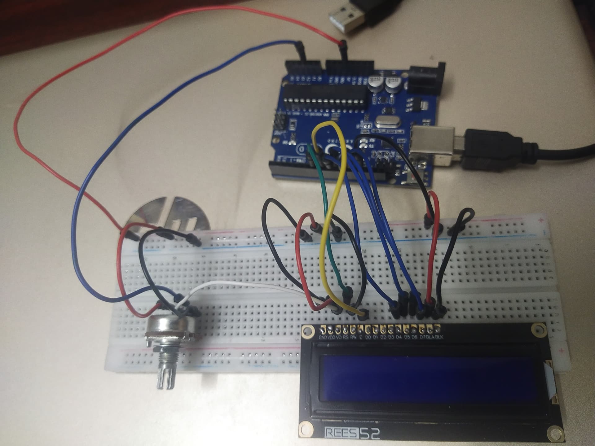
I hope these are sufficient. (Please check the soldering too, I'm a beginner at soldering)
The wiring follows tge same colour scheme as in the circuit diagram, except the orange in diagram is replaced with a yellow wore and the yellow in diagram is replaced with a white wire.
The backlight pot seems to have an extra wire. The blue wire on the left. The pot should ony have G 5V on the outside pins, and the wiper connects to the BRIGHT pin, 3rd from the left I think.
The blue wire on the potentiometer is not extra. It is coming from an Analog pin which I've used to perform analogRead to check if the potentiometer is working correctly or not.
Once you confirm the POT is working, remove the bluw wire in case it is having some side effect.
NOTE: Unless you just happen to have one of the two good brands of bread board, they are famous for bad connections. wiggle all the wires to check. The pictures are not good enough to truly tell, but the wiring seems to be right.
Thanks for this, but before I soldered the head pins, I just connected the wires and the LCD Screen and this problem was still there. The display would only glow up on a certain angle (with just the blank blue screen) and that's when I realised that I had to solder the head pins. The problem of the lcd glowing only when held at a certain angle was fixed, but the screen is still blank, so I think the soldering is not an issue. Tomorrow I'll try to change the position of the lcd and try again, though I don't think my bread board is of bad quality. I'm sorry for everything here, I'm just a beginner, I wrote my first Arduino code not less than a week ago!
Not at all, I was born 1942. Played with my first computer in high school 1959, it was analogue machine for student experiments donated by Ferranti Packard Canada.


