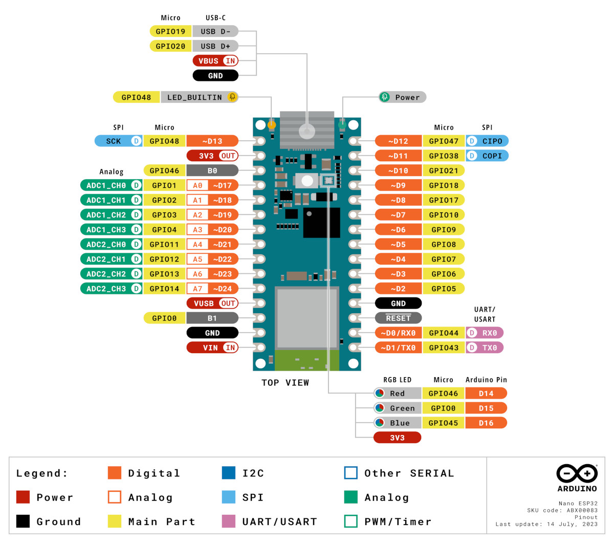
Dear Arduinists, I am trying to make a battery operated (2x 9v in parallel) data logger for a weight sensor. It should write its data to SD, so far everything works when I am hooked up on the console. When I go on battery power the Arduino does not write anything, even in the bare SD test sketch posted below. I use the standard ISP pins (SCK13, SS10, MOSI11, MISO12). One thing I do notice is that the internal led, which I use for debugging, does not react and stays on permanently. I assume this has to to with it being connected to SCk pin 13?
On the hardware: my battery set up give a healthy 18v to the Vin. A simple blinking led sketch works fine on battery power, showing that the basic power supply set up is fine. The simple SD write sketch below works on console, but not on USB connected to an adapter, which makes me suspect it has something to do with power supply? Can anyone point me in the right direction?
//Debug pins
const int ledPin = LED_BUILTIN;
const int checkPin = 2;

// Libraries to include
#include "SPI.h"
#include "SdFat.h"
SdFat SD;

// All variables around SD card logging are below
#define SD_CS_PIN SS
File metaData;
String metaString = "";


void setup() {
  // Wait until serial port opens for native USB devices, sets port 9600 for coms
  Serial.begin(9600);
  while (!Serial) {
    delay(1);
  }

  // Debug LED & signal pin
  pinMode(ledPin, OUTPUT);
  digitalWrite(ledPin, LOW);
  pinMode(checkPin, OUTPUT);
  digitalWrite(checkPin, LOW);


  // Boots SD Card Reader

  Serial.print("Initializing SD card...");

  if (!SD.begin(SD_CS_PIN)) {
    Serial.println("initialization failed!");
    return;
  }
  Serial.println("initialization done.");
}

void loop() {

  Serial.println("Loop started");
  digitalWrite(ledPin, LOW);
  digitalWrite(checkPin, LOW);
  delay(1000);
  metaString = String(millis() / 1000);
  saveMetaDataSD();
}


// Function: Saves metaData on SD
void saveMetaDataSD() {
  digitalWrite(ledPin, HIGH);
  digitalWrite(checkPin, HIGH);
  delay(1000);
  digitalWrite(ledPin, LOW);
  // so you have to close this one before opening another.
  metaData = SD.open("metaData.csv", FILE_WRITE);

  // if the file opened okay, write to it:
  if (metaData) {
    metaData.println(metaString);
    metaData.close();
    Serial.println("written to metaData.csv");

  } else {

    Serial.println("error opening metaData.csv");
  }
}
Not according to the datasheet Jim. I read the SD was unstable when the Arduino was fed less than 10v, that's why I went for 2x 9v in series. As I said, a simple blinking led sketch works fine with this set up.
The voltage regulator on the Nano ESP32 will operate in different modes depending on the input voltage and the load current. The different modes have different noise and load transient characteristics. It looks like the design was copied directly from the data sheet, which was optimized for a 12V input.
All I can suggest right right now is to try it with a 12V supply and see if it works.
Thanks Jim, I will try and see if this works and get back to you. Any idea why a simple sketch works, but a slightly less simple sketch does not? Also, 5v DC via the USB connection should be more or less impossible/useless if I follow your train of thought?
It will still work with a 5V input but it may not be as efficient. The data sheet doesn't provide data with a 5V input and a 3.3V output. I don't know why one sketch works and another doesn't but it will depend on the current used.
So I have hooked up the Nano ESP32 to a lab DC power supply. When I power it on it does not work, it has some basic power conusmption, @12v/20mA, @10v/22mA, so all roughly the same net power consumption.
Now the weird thing: if I hook it up to the console first, it works fine. Next I power it additionally from my 12v DC source. When I detattach the USB it continues working just fine. It draws 12v/30mA, and writes data to the SD card like a charm. I tried it with additional sensors, all works exactly as I intended, it just cannot boot on a DC source! I did notice a small spike in power consumption on power on (12v/30mA, thgen it drops down to 12v/20mA).
I did, no boot, appearantly. After I do so the arduino does consume some power (12v/20mA) but not the (12v/30mA) I see when it should be running normally.
I have tried with both a DC power supply and a voltage regulator circuit (12v Zener diode, and a 150Ohm resistor) connected to my batteries.
I'm out of suggestions. I would suspect that the nano ESP32 is damaged somehow.
Hopefully a Nano ESP32 expert will join the topic and can help if possible.
That would be my prefered option, because I suspected Pin 13 would give me trouble.
The standard SPI pins are like the pinout above(SCK=13, MISO=12, MOSI=11, CS=10), I tried those and I got the SD to work, on USB power, no problem. I thought about using SPI.begin() to reassign the SPI pins to (SCK=8, MISO=12, MOSI=11, CS=9). As said I would like to avoid using pin 13.
At this moment I am randomly trying, which is not a very optimal way to move forward.
You can't reassign CLK from 13 to anything else if you are using hardware SPI
I'd keep clear of GPIO06 to GPIO11 because these could be used internally by the ESP32.
Try using GPIO14 (A7) for the CS/SS of the SD card
Print out the values of the SPI pin macros CLK, MOSI and MISO to verify that these are infact 13, 11 & 12 respectively. However, if you had success with the SD card, I guess these must be right.
After replacing the board with a new arduino I realized the problem was in the initialisation. The while statement pushed it in a holding pattern while it was waiting for the serial connection to come online. This explains why it did work when starting using the serial connection + dc supply and then decoupling the USB, whilst not working when I tried to start it using DC only.
It now works steadily on a broad range of voltages, directly powered by a 9v battery.


