Hi guys,
i'm struggling with a strange behaviour in my drone project and need some help.
The Hardware-Settings:
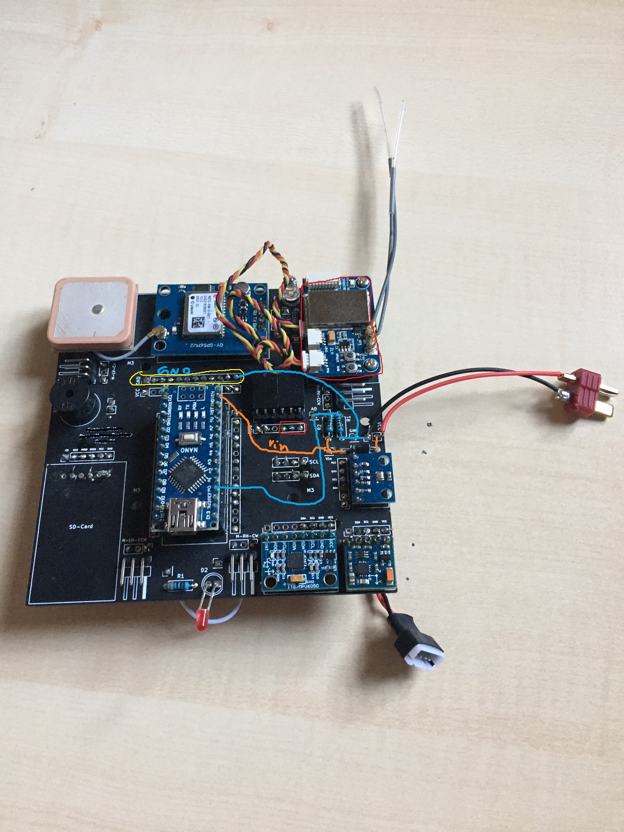
I use a FlySky X6B Receiver for receiving Throttle-inputs etc. from my FlySky FS-i6x RC. The X6B is connected via PPM-Output to the Arduino Nano Pin D2. GND is connected to GND of Nano and VCC to the 5v of Nano.
I want to power the whole electronics of my quadcopter with a 3S Lipo (12.6 V) via Vin. I placed a diode, to get a voltage-drop and protect USB-Port. When the Lipo is connected, the incoming voltage at the Vin is round about 11.5 V (Nano gets warm, but not much)
See schematic attached.
Sketch I use (its only the RC part of the whole Drone Sketch): i found it on a homepage, i already flew with it several times (in another hardware build). So it should work (see Test-Case 1)
#define RECEIVE_PIN 2    // Pin 2 geht z.B. auch
#define CHANNEL_AMOUNT 8
#define DETECTION_SPACE 2500
#define METHOD RISING

int ch[CHANNEL_AMOUNT + 1];

void setup()
{
Serial.begin(115200);
pinMode(RECEIVE_PIN, INPUT_PULLUP);
attachInterrupt(digitalPinToInterrupt(RECEIVE_PIN), ppm_interrupt, METHOD);
}

void loop()
{
ppm_write();


}

void ppm_write()
{
static unsigned long int t;
if (millis() - t < 100)
return 0;
for (byte i = 0; i < CHANNEL_AMOUNT + 1; i++)
{
Serial.print("Ch ");
Serial.print(i);
Serial.print(" ");
Serial.print(ch[i]);
Serial.print("\t");
}
Serial.print("\n");
t = millis();
}

void ppm_interrupt()
{
static byte i;
static unsigned long int t_old;
unsigned long int t = micros(); //store time value a when pin value falling/rising
unsigned long int dt = t - t_old; //calculating time inbetween two peaks
t_old = t;

if ((dt > DETECTION_SPACE) || (i > CHANNEL_AMOUNT))
{
i = 0;
}
ch[i++] = dt;
}
Test-Case 1: Powering the Arduino via USB
Everything works! The serial monitor shows the pulse of every channel between 1000 and 2000. The Nano dont hang-up. Code looks fine.
Test-Case 2: Powering the Arduino with a 3S Lipo (12.6 V) via Vin, also connected via USB to read the serial Monitor
Step 1: RC is turned Off. Everything works, like in Case 1. Only the pulse of every channel is zero. Nano dont hang-up. Receiver LED blinks, searching a transmitter signal.
Step 2: I turn the RC on. immediately the LED on the X6B receiver stop to blink and shines constant (= connection between receiver and transmitter) AND the Nano hang-up! I know it because the serial monitor stops sending pulses, instead there are the ??⸮⸮??? Symbols (like when you have the wrong baud).
Furthermore i testet it with a constant blinking LED in a modified sketch, an the blinking also stopped when i turned on the RC. Therefore i think the Nano hang-up and stop working correctly.
What causes this problem?
I think its a hardware problem, but i cant figure it out exactly. What else could i test?
FYI: I had disconnected the Motors VCC/GND and GND/Signal of the ESCs. But also with a connection it didnt work.
Thanks for your help!