Need coding help with latching/bistable relay module

Hello All;

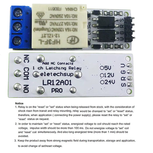
I am having some difficulty with a latching, dual coil relay. I will be using this relay to turn on a gas heater. In the future, this logic will be incorporated into my thermostat control project, but for now I am only doing a proof of concept with the relay, using a push button for the control. The relay is question is a Eletechsup LR12A01 Pro. There are four pins on the control side (VCC, GND, RESET, SET) and three on the output (NO, COM, NC). Here is a picture:

Here is a link to their product page, including a downloadable datasheet: LR12A01 DC 5V Magnetic Latching Relay Module

I have this connected to an ESP32-C3 Super Mini dev board. I also have a single push button which will pull a pin to ground on activation. My problem appears to be that whenever I have both the SET and RESET pins connected to pins on the ESP32, they are locked in a fight with one another. It's as if they are both attempting to SET or RESET the relay at the same time.

However, I can manually SET and RESET the relay by grounding the pins one at a time. When I do this I can hear the relay click, so I know it's working. To be more accurate, I can touch the pin of the one not last "clicked" with either GND or VCC to hear the relay click again. I suppose those pins are just looking for a change in the voltage, but I am not sure.

I scraped together a very basic sketch that I derived from others in the forums (and greater Interwebs). I have tried every combination of pulling the pins HIGH and/or LOW to trigger the relay, during both the initial void Setup() routine and my button's click event but have had no success. I should point out that occasionally the button click event does not register (i.e. I can see the Serial output had not updated). I think may have something to do with the SET/RESET fight I mentioned earlier, but perhaps not.

Could someone please look at the code below and tell me if I am making an obvious mistake?

//SAMPLE CODE FOR ESP32 C3 SUPER MINI

#include <OneButton.h>            // This button library includes a deBounce function 

#define LED_BUILTIN 8             // Internal LED
const int LEFT_BTN_PIN  = 0;      // SET Button pin
const int RELAY_PIN_SET = 6;      // SET control for relay
const int RELAY_PIN_RES = 7;      // RESET control for relay
bool rly_state          = 1; 

OneButton buttonLeft(LEFT_BTN_PIN, true);


void setup()
{
  Serial.begin(115200);
  while(!Serial){;}
  buttonLeft.attachClick(clickLeft);        // This attaches the click event to the OneButton control
 
  pinMode(LED_BUILTIN, OUTPUT);             // This is the ESP32's LED
  pinMode(RELAY_PIN_RES, OUTPUT);           // This is the relay's RESET pin
  pinMode(RELAY_PIN_SET, OUTPUT);           // This is the relay's SET pin

  digitalWrite(LED_BUILTIN, HIGH);          // LOW = ON; HIGH = OFF (with the ESP32-C3)
  digitalWrite(RELAY_PIN_SET, HIGH);         // Start with the relay in a known state
  delay(1000);
  
  digitalWrite(RELAY_PIN_RES, LOW);         // 
  delay(200);                               // Pulse the RESET pin HIGH then LOW to put into RESET state (N.O. is open)
  digitalWrite(RELAY_PIN_RES, HIGH);        // 
  
}


void loop()
{
  buttonLeft.tick();
  delay(50);
}


void clickLeft() 
{
  if (rly_state)                                  // if the relay should be latched to the SET state
  {                     
    digitalWrite(RELAY_PIN_SET, LOW);             // Set the SET pin HIGH
    delay(200);                                   // Hold the pin HIGH long enough to latch
    digitalWrite(RELAY_PIN_SET, HIGH);            // Set the SET pin LOW
    digitalWrite(LED_BUILTIN, HIGH);
  }
  else                                            // if the relay should be RESET
  {                                
    digitalWrite(RELAY_PIN_RES, LOW);             // Set the RESET pin HIGH
    delay(200);                                   // Hold the pin HIGH long enough to latch
    digitalWrite(RELAY_PIN_RES, HIGH);            // Set the RESET pin LOW
    digitalWrite(LED_BUILTIN, LOW);
  }

  Serial.println("State = " + String(rly_state));
  rly_state = !rly_state;                             // toggle the relay state
}
Did you ever set down and write out in words exactly what you want to happen and the order needed for that to happen? How did you determine what code to scrape together and what code to bypass? If you did, please show us a copy.

Hi, Paul!

I'm not sure I follow your question. I want to press the button to toggle the relay, and then press it again to toggle the relay back. Eventually, I will be toggling the relay with the aforementioned thermostat control project. Rather than a button press, the relay will be toggled based on values pulled from a temperature sensor.

When the system boots/reboots/resets, I want the relay to be in the original Normally Open position. IOW, I do not want the heater on.

I'm no HVAC expert but I question your thinking here. If it's a true latching relay it will maintain its state when power or set/reset control is removed. If the controller, whatever that is, goes to la-la-land what's to keep the relay from energizing something long after it should have been shut off?

1 Like

Hi Doug,

We're putting the cart before the horse here. I said in response to the other reply that I want the relay to go back to a normally opened (NO) position when the MCU controller boots, reboots, or restarts. You are correct about what the latching relay's behavior should be on power loss, and the item I purchased does indicate it is a latching relay. I have no reason to doubt that.

My problem is that I cannot get the relay to latch or unlatch at all when it is connected to the MCU, as I indicated in my original post.

What is that connected to?

What happens if you connect them to 3.3V instead of ground? Remember, when an ESP pin is HIGH, it outputs 3.3V.

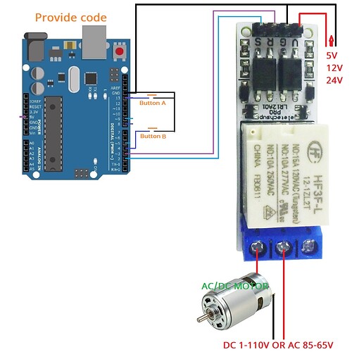
I don't have any latching module to test with, but just to start from the beginning: did you ever have a look at the Arduino sample code and diagram (where's yours?) included in the manual, and tried it to check if it helps in any way?
I mean this diagram:


and this code:

int INA = 3;
int INB = 2;
int buttonA = 13; //Set Button A as blue button, connect to Pin 13 
int buttonB = 4; //Set Button B as red button, connect to Pin 4 

void setup() {
  pinMode(INA, OUTPUT);
  pinMode(INB, OUTPUT);
  pinMode(buttonA, INPUT);
  pinMode(buttonB, INPUT);
}
void loop() {
  if (digitalRead(buttonA) == LOW) 
    {
      digitalWrite(INA, HIGH); 
      delay(100); //100ms pulse signal 
      digitalWrite(INA, LOW); 
    }
  if (digitalRead(buttonB) == LOW) 
      digitalWrite(INB, HIGH);
      delay(100);//100ms pulse signal 
      digitalWrite(INB, LOW);
  }
}

PS: the only thing I'd change, I think an INPUT_PULLUP for the buttons should be used..

1 Like

Hi, Docdoc!

Thank you for the reply! I currently have the relay being powered by the 5v pin on the ESP32-C3 Mini. Your diagram appears to be using a separate 5v supply from elsewhere. That seems like a good place to start.

The code you posted is very similar to my own, and I think I have already tried this exact snippet in previous tests.

I have another relay (non-latching) that I was able to flip flop back and forth using a single output pin from both the C3, as well as, a ESP-WROOM-32 dev board. In that case, I only had to ground the RESET pin to toggle. Maybe my new relay is not as tolerant. :thinking:

I will give this a try and report back. Cheers!

Hi, Paul!

I currently have the relay connected to the 5v line and a ground pin on the ESP-C3. The SET and RESET pins are connected to pins 6 and 7, and they are configured as outputs.

When I was performing my goofy manual test, I was connecting the SET and RESET pins to a GND and 3.3v rail coming from the ESP. The relay flipped and flopped when doing this. I believe I also tried a 5v source and it worked as well.

If you disconnect both relay inputs, then connect the S input to ground for a moment, to set it, then disconnect it, then connect the R input to 3.3V for a moment, does that flip the relay? If so, disconnect R again and now connect S to 3.3V for a moment. Does that flip the relay again?

I'm wondering if a 3.3V level, being less than 5V, is low enough to flip the relay.

I also agree with @jim-p, connecting the ESP output pins to this relay could be damaging the ESP. A 5V Arduino would be safe, but maybe not a 3.3V Arduino. A couple of transistors & resistors would protect it and hopefully control the relay as desired.

1 Like

If you disconnect both relay inputs, then connect the S input to ground for a moment, to set it, then disconnect it, then connect the R input to 3.3V for a moment, does that flip the relay? If so, disconnect R again and now connect S to 3.3V for a moment. Does that flip the relay again?

YES, on both accounts! I need correct something I said earlier. If I try to connect the S or R inputs to the 5v output on the ESP or relay, it does NOT trigger the relay. I could have sworn that was the case, but my latest test proves otherwise.

A 5V Arduino would be safe, but maybe not a 3.3V Arduino. A couple of transistors & resistors would protect it and hopefully control the relay as desired.

The reason I chose the ESP architecture is because I wanted to use ESP-NOW to transmit temperature data from the C3 to an ESP32 which will control the relay. Did some googling and it appears that no ESP has 5v data pins. Oddly enough, I am able to drive an LCD 1602 (with I2C backpack) and an KY-040 rotary encoder (both 5v) with these ESPs with no issues. I have an Arduino Pro Mini and Nano, both of which are the 5v variants.

For the purposes of this latching relay test. I think I will try two things:

  1. Provide a separate 5v supply for the ESP-C3 and test my original code.
  2. Swap out the ESP-C3 for an Arduino Nano (5v) - and test my original code.

I will report back here with my findings. If there is no change, then I will shift my focus to the Arduino. At which point I will need someone's guidance on the proper code to use.

I expect ~1s LOW pulse to S sets one state, ~1s LOW pulse to R sets another state.
But play with 5V arduino, ESP32 gpio pins are not 5V tolerant, even if it might work (for a while).

See post #8

From the relay data sheet we can see it takes 90 mA current to trigger a set or a reset. The outputs of your ESP32 can't supply that much current by themselves. Do you have any NPN transistors that you can use to build a small circuit to supply the proper amount of current?

That seems to confirm my theory

Your relay module contains opto-isolators (those black components with 4 pins each). It would seem that the (5-3.3)=1.7V voltage drop across the opto-isolator's input is enough to trigger it, which in turn triggers the relay (via those transistors, the small black components with 3 pins each).

When connected to a 5V Arduino, when the output pin is HIGH, it would output 5V, so the voltage drop across the opto-isolator's input would be 0V, so it wouldn't be triggered.

You don't need to abandon your ESP. You just need to add a couple more transistors to overcome the unwanted triggering problem (and protect the ESP output pins from damage due to being connected to 5V).

@thehitponcho the transistors don't have to be 2N3904. Lots of similar transistor models will also work, but check with the forum first.

1 Like

Happy days! My code is now WORKING with the substitution of my ESP32-C3 with a 5V Arduino Nano. At least it appears to be for now. The problem must have been the under-powered ESP pins.

My attempts at testing with an external 5V supply did not proceed as my cheapo breadboard power module had a faulty 5V rail. I will, however, try this once I source another supply. I read in multiple places that separating the MCU supply from the relay (then tying the grounds together) would be a more prudent move (as illustrated in @docdoc 's schematic above).

I haven't yet given up on the ESP32-C3 for now. I may not be able to drive the relay with it but I can still use them to pass the sensor data and perhaps send a signal to the Nano to flip the switch. I may even use @jim-p 's transistor trick, once I get my hand on some.

Very many thanks to ALL of you who participated in helping steer me to the correct solution. That was very kind of you. This was my first post, so you have my apologies if the threads seem to jump around. I haven't quite figured out this formatting business.

You were right about those opto-isolators. I googled the part number and that's sure what they were. I am going to proceed with using the Arduino for now but will hopefully return to the ESP once I get my hands on some transistors. Thanks for your help!

[kidding]
Reading you, this thing came to my mind:
"All brontosauruses are thin at one end, much MUCH thicker in the middle, and then thin again at the far end . That is the theory that I have and which is mine, and what it is too."
[/kidding]

PS: sorry for the OT, btw is this too "Brit" to be recognised? :wink:

@docdoc I fart in your general direction. Your mother was a hamster and your father smelt of elderberries

3 Likes