Total noobie question: I am struggling to write code for two buttons from a single SPDT momentary toggle switch with [ON] OFF [ON] configuration. and I would appreciate an example to follow
The objective is to pass FLAPS UP or FLAPS DN to Microsoft Flight Sim 2020.
The aircraft I am replicating has just one toggle switch controlling the flaps while the examples I have been able to find all use a lever that moves a slide potentiometer.
I was following an example using a button matrix code but it can't work for just two buttons. The remaining items on this controller are all emulated by sliders - Throttle, Fuel Mixture and Carb Heat so I can't add them in to make a viable matrix.
You could do a full 6 axis HOTAS w/10 bit ADC on a low-end board with a button box if you take small steps like 1 switch at a time! The road ahead is long, wide and open.
First thing I would do with your switch is wire it to 3 pins and see what I could find out.
Have you done any of the Tutorial Examples loaded in your IDE if you have that or a board of your own? There is an Arduino simulator named Wokwi... but I prefer actual real.
Thank you for your encouragement and suggestions. I am working through those suggestions and many other seemingly relevant options I found while exploring this rabbit hole. I would add “rocky” to the description of the road ahead. Trying to keep my head up.
momentary would mean: only as long as a mechanical force is applied to the switch the switch goes into position closed
as soon as the switch is released the switch goes back to position opened
or vice versa mechanical force applied position opened
switch released position closed
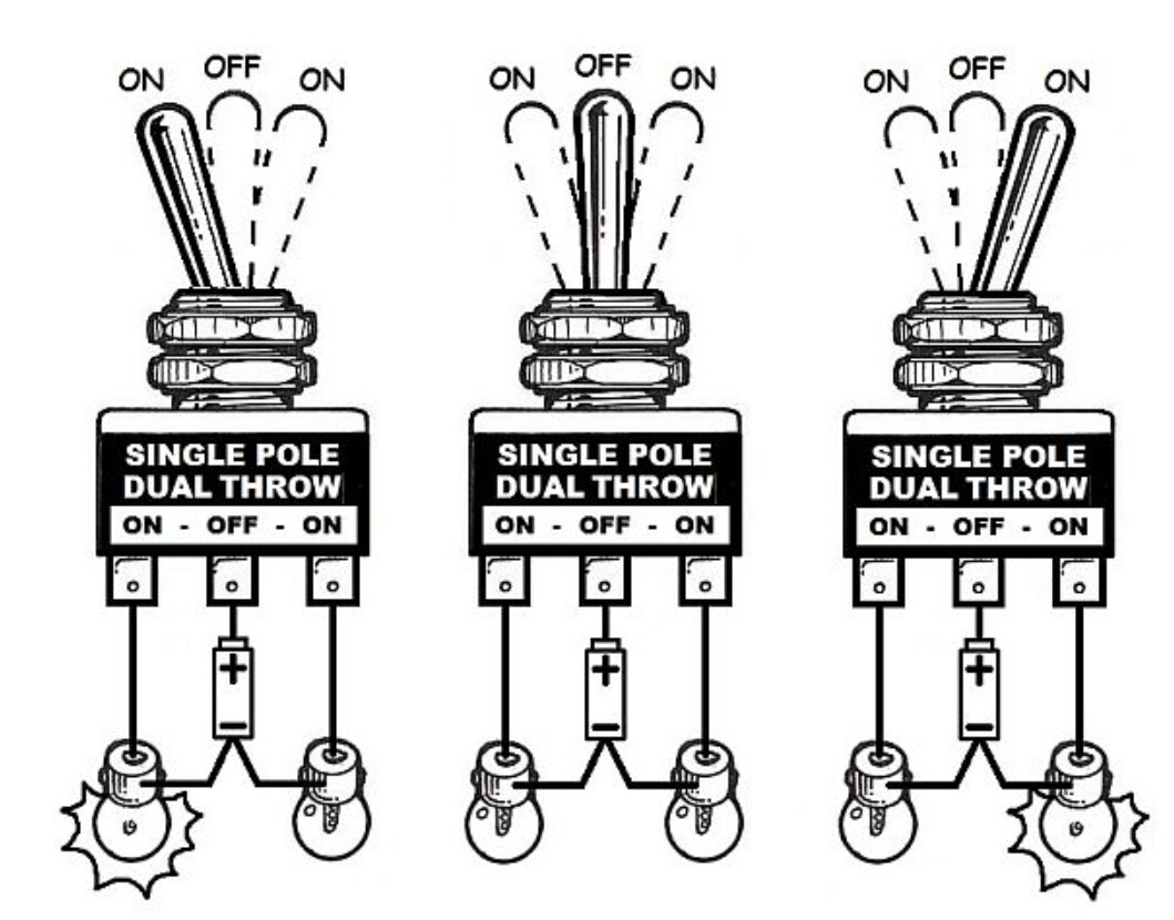
and a switch that does [ON] OFF [ON] usually looks like this
with including to have a middle-position (= the off-position) where both contacts are opened
You should post a much more precise description what kind of switch you have and how switch-positions are related to
Do you mean a switch that without applying a mechanical force to the lever the switch stays in middle-position off = opened
and depending on the direction of the mechanical forces the contact on the left
or
the contact on the right closes?
but as soon as the lever is released the levver goes back to middle-position?
inside your code shall the command
FLAPS UP / FLAPS DOWN by applied just as long as the switch is ON
to enable driving FLAPS UP / DOWN for a small percentage
or shall a short tip on the switch make the FLAPS go fully up / fully down ?
A simple button manager, which debounces the button and determines the subsequent action, can be easily programmed in C++.
All you need is a structured array with all the relevant data and a timer. A timer function can be easily derived from the IDE example BlinkWithOutDelay.
Just give it a try.
That is not how flaps work. They are analog. While the switch is held the flaps move up to end of travel. It literally does not need to detect transition, in small planes it is electro-mechanical.
Your quotation quotes both descriptions which one do you mean?
to be more precise
While the switch is held the flaps move towards up to end of travel.
and stop immidiately in an inbetween position if switch is released?
Hi Stefan,
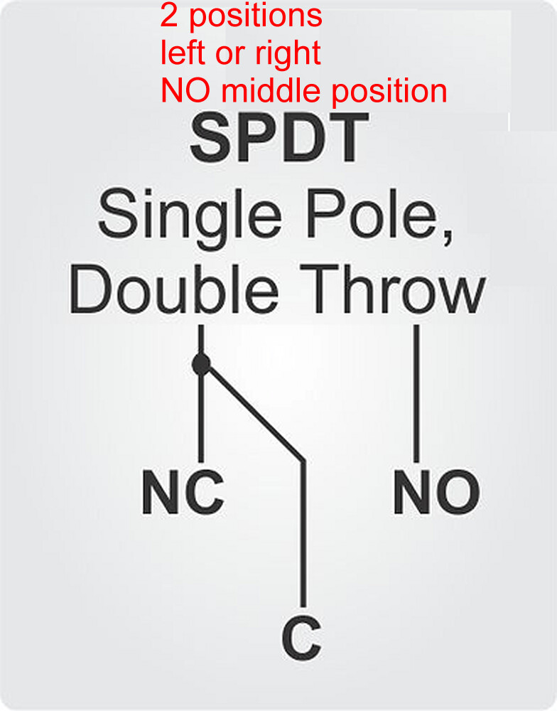
To me, your two diagrams are electrically identical. In the top one, common (“C”) connects, momentarily in my case, either to normally open “(NO”) or normally closed (“NC”). There are three terminals, just like the bottom diagram. If there IS a relevant difference, it would be an important learning point for me to know.
For realism and ergonomic consistency, I would obviously like the flaps to retract (go up) when the toggle is held up and to extend when the toggle is held down. However, I have found that the toggle handle operates opposite to the contacts. So, when the toggle is pressed up, the middle and bottom terminals are connected. All my toggle switches are manufactured by Carling but I doubt if other manufacturers products are different.
Either way, I can cope with that aspect as long as I have code to recognise the two possible inputs from the switch and pass them to msfs.
I am using a Micro Pro, which has a chipset that can be recognised as a HID in windows.
Hi Goforsmoke,
You are correct that modern experimental aircraft these days use a programmable electronic flap controller. I am a private pilot and have flown a real Vans RV-7 equipped in this way. As a matter of fact, I am almost finished building my own actual RV-9 variant.
In MSFS, I am using Deejing’s freeware Vans RV-7 addon aircraft. In that model, a short press in either direction moves the flaps to the next programmed position in that direction. A sustained press moves the flaps continuously to their end position in that direction. That is almost correct, in my RV-9, a long press (>1 second) on the flaps toggle will move the flaps to the end position. You don’t have to hold it. That is necessary in ‘touch-and-go’ landings where you want to transition immediately from full flaps to no flaps, ideally without having one hand fully occupied on the flaps switch when the throttle also needs attention.
Anyway, this is all a digression from our topic. I just want to know how to code for two momentary buttons. Later, I need to do this alongside three potentiometers for throttle, fuel mixture and carb heat. Based on your advice to take things step by step, I just want to get the two momentary switches in my flaps toggle working for now
electrical
This kind of switch would deliver either a infinite enduring
flap up
flap up
flap up
flap up
flap up
......
or an infinite enduring
flap down
flap down
flap down
flap down
flap down
.....
signal
this one has three positions
left on - middle off - right on
the middle-position is spring-driven
if it is a momentary switch the signal
flap up would only be given as long as you push the lever up
flap down would only be given as long as you push the lever down
if you release the lever there is
no up-signal / no down-signal
no up-signal / no down-signal
no up-signal / no down-signal
...
until you push the lever again up or down
take a look into the toggle-library
This library dlivers a lot of functions
I think if you adapt the 3-pin toggle-switch to your needs this will work
if you look at these code-lines
  if (sw1.UPtoMID()) {
    Serial.println(F("sw1: UP⇒MID"));
  }

  if (sw1.MIDtoDN()) {
    Serial.println(F("sw1: MID⇒DN"));
  }

  if (sw1.DNtoMID()) {
    Serial.println(F("sw1: DN⇒MID"));
  }

  if (sw1.MIDtoUP()) {
    Serial.println(F("sw1: MID⇒UP"));
  }
half of the functionality that you need is done inside these function-calls
You wrote
short push move to next pre-programmed position
push longer than a second move to end-position
detecting the length how long the lever is pushed could be done by measuring time-differencies
emphasizing on differencies
if MIDtoUP() is detected store first snapshot of time "MidToUp_detected"
if UPtoMID() is detected store a second snapshot of time "UpToMid_detected"
the calculate UpToMid_detected - MidToUp_detected
if less than 1000 milliseconds
==> move to next proprogrammed position
else // Which is more than 1000 milliseconds
==> move to end-position
one step at a time means
start with the example-that does simply this
  if (sw1.UPtoMID()) {
    Serial.println(F("sw1: UP⇒MID"));
  }

  if (sw1.MIDtoDN()) {
    Serial.println(F("sw1: MID⇒DN"));
  }

  if (sw1.DNtoMID()) {
    Serial.println(F("sw1: DN⇒MID"));
  }

  if (sw1.MIDtoUP()) {
    Serial.println(F("sw1: MID⇒UP"));
  }
write a small code that does move to ONE next pre-programmed position
learn what arrays are
write a small testcode that does all 3 or 5 or how many ever pre-programmed positions by using an array
write a testcode that increments / decrements through all pre-programmed positions
each testcode will be put into its own function.
Then you can mount together all functions the same way as the lading gear is mounted from multiple components
tire left / right (build from tube and air-valve)
ball bearing
screws
etc.
Yes, exactly. In early and light planes, flaps and gear were/are hand-cranked into position. By the late 30's, weight permitting, electric motors took care of more and more of that though big planes got hydraulics. You should see what Rotol did for variable pitch props, Curtiss-Wright did much the same.. all electric.
He needs pin state logic where bounce is too short to matter.
edit: well no, he needs more but caution: the flight sim may carry out the timing and actions he describes and need no help. i would debouce the switch pin and pass HID a switch sense to see.
Where the contact on the switch is doesn't force where the wire to it connects and the program in the Arduino can watch for press periods and automate the action.
I didn't get a ticket but I've dipped into real, simulated and history of flight more than average. My paper airplanes have straight wings with a spar and cambered surfaces. they also tend to be flying wings, I had Ralph S. Barnaby's book covering his 1910 designs.
Thanks to all who replied. I have tried working my way through the examples but concluded in the end that native Arduino code written in the IDE is not the right tool for me. I have no interest in Arduino outside of flight simulation and building a cockpit for the sim that will increasingly mimic my real aircraft (did I mention I am at an advanced stage of building a Vans RV-9?). Therefore I have no need of a proper programming language. I have discovered that Mobiflight is the ideal tool for my purposes as it is specialised to interpret between sim controls and (some) Arduino boards and is much easier to learn, being much more limited.
Using Mobiflight, I was able to configure, not only the flaps switch but also the sliding potentiometers that are moved by my carb heat, throttle and fuel mixture controls. The flap switch now correctly interprets a short press to move to the next position up or down as appropriate and a longer press to move fully up or down.
I was not expecting a long discussion of switch typology, as the point of the thread was really about code for two momentary buttons. However, I believe my original post was correct in describing my switch as [on] off [on]. In building the real-life electrical system and panel for my plane, brackets around [on] or [off] always indicated a momentary position and "on" always means the circuit is closed. "Off" shows that the circuit is open and, without brackets, it is a maintained position. This is precisely the type of switch I am using and I now have it controlling the sim precisely as it should.