thanks.. I'll do that..
ok,, I have all pins connected for use on a UNO.. i have the sketch loaded.
( the one without the serial ) I tried it.. I just get full displays of red. I think something is a miss ? INO says DONE uploading... no errors.. so I think i might have a pin mixup ? I have CLK to pin 3 , data in to pin 4, CS-second to pin 5, SC-min to pin 6, and CS-Hr to pin 7..
I'll check back later..
i have done this.. sketch loaded ok, but it does not function.. Just all leds. what am i missing here..?
Do you mean a modified version of the simpleClock example or the POST example? The POST example starts with all the Leds on for 5 seconds and then cycles through the Leds one at a time. It does it in order seconds, minutes then hours.
The POST is designed as a power up test to make sure all the Leds are working. The POST function would normally be called at the end of setup() to make sure the hardware is working.
Using the 8X8X4 display is more complicated than I first realized. It is configures as one long shift register. It is an expanded version of figure 3 on page 13 of the data sheet. This means the displays are not individually addressable as it comes. Data for displays further down are shifted through the previous ones.
To use them as I proposed with common CLK and DIN and using CS(LOAD) for selection means you also have to cut the CLK and DIN lines and connect the IN sides together.
yes, without serial... all the leds just turn on, and stay on...
Question...just so i'm thinking right.. the pins described are what is shown on the UNO board.. digital 1-13. if so, then that is what i am using.. pins 3-7.
can we just cut it down to just 1 8x8 this is all i really need for testing my display, I can just shift connections as i am testing.. Really not a need to use them all, But when it comes time, Then I'll use 3 of the boards to do the project..
Sure. Just connect the Arduino to the display board and ignore what happens past the first display. They will change as the data gets shifted down and loaded as you update the first display. This is what I did.
You can leave the power, CLK and DIN connected and just move the CS to pins 5, 6 and 7 to test the seconds, minutes and hours on the first display.
ok,, Something still isn't right, I just get all leds on.. I tried a different sketch i found, just to test and make sure the display drivers are working ok.. I found something that scrolls letters..So they are working ok,, I'm not sure what isn't right with the code you have... If i tried the one with serial, it gives errors,,, but the one without serial uploads ok,, Just doesn't function.. Hmmm
I have been trying to develop the most efficient way to use MAX7219 ICs to run the hours,minutes and seconds for an analog clock. This involved shifting data into the ICs in parallel and then using the LOAD/CS on the individual ICs to pick which one is actually updated.
Unfortunately there don't appear to be any ready made boards in this configuration. There are boards with 4 8X8 dot matrix displays where the ICs are connected as a long shift register. These would require cutting traces and rewiring to use as I did the design. One suggestion was to use them as is with the generic LedControl library support. I figured that it would take 3 times as long to update since 3 ICs would be updated each time.
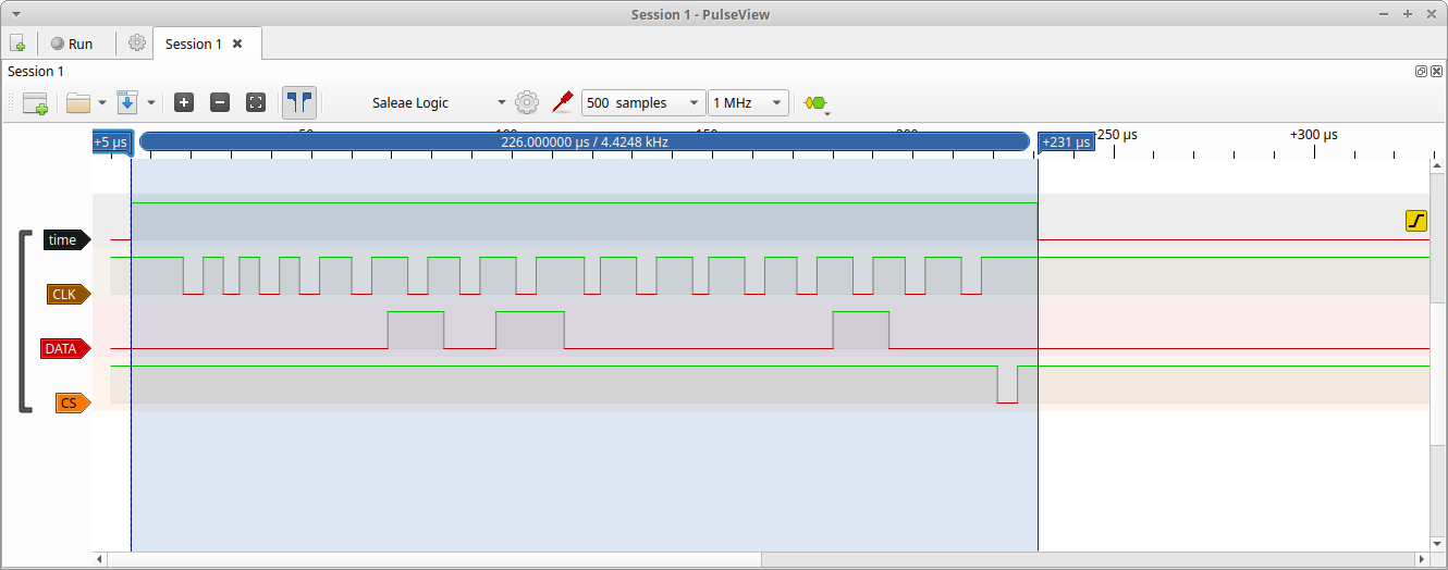
The question I had was "How bad would that be?". I devised some experiments to answer that question. First I took the simpleClock example and added code to set the built in Led high at the beginning of the clock update and low at the end. I used the built in Led to see if the flash would be noticeable and give some idea of the time. Next I connected a logic analyzer to get the time the built in Led was on as well as the MAX7219 control lines for the seconds update. As can be seen it takes 226usec to do the update.
Next I modified the simpleClock example to use the LedControl library to equivalent function. The code is below.
/********************
 *
 * A simple clock test
 *
 *******************/
//#include <Streaming.h>
// #include "Aclock.h"
#include "LedControl.h"

// common clock and data
const uint8_t clk_line = 3;
const uint8_t data_line = 4;
const uint8_t load_line = 5;

LedControl lc=LedControl(data_line,clk_line,load_line,3);  // only using 3 displays
const uint8_t seconds = 2; // display 2
const uint8_t minutes = 1; // display 1
const uint8_t hours = 0; // display 0

// starting time
uint8_t timeSec = 0;
uint8_t timeMin = 0;
uint8_t timeHr = 0;
unsigned long waitTime = 1000; // wait a second
unsigned long lastTime,curTime;
bool updateMin = false;
bool updateHr = false;

 void setup()
{
  char inBuffer[10];  // input buffer
  char* chrPos;       // pointer to found chr
  Serial.begin(115200);
  // initialise clock
    lc.shutdown(hours,false);
    lc.shutdown(minutes,false);
    lc.shutdown(seconds,false);
  /* Set the brightness to a medium values */
  lc.setIntensity(hours,8);
  lc.setIntensity(minutes,8);
  lc.setIntensity(seconds,8);
  /* and clear the display */
  lc.clearDisplay(hours);
  lc.clearDisplay(minutes);
  lc.clearDisplay(seconds);
   // set starting time
  Serial.println("Enter tine hh:mm:ss");
  while (Serial.available() <= 0) {}; // wait for data
  // data available
  Serial.readBytesUntil('\n', inBuffer, sizeof(inBuffer)-1);
  // assume we have valid data
  timeHr = atoi(inBuffer);      // convert hours
  chrPos = strchr(inBuffer,':');   // find delimiter
  chrPos++;  // skip delimiter
  timeMin = atoi(chrPos);  // convert minutes (one past delimiter)
  chrPos = strchr(chrPos,':');   // find next delimiter
  timeSec =  atoi(chrPos+1);
//  Serial << "hours "<<timeHr << " Minutes "<<timeMin<<" Seconds "<<timeSec<<endl;
  lc.setRow(seconds,(timeSec>>3),(1<<(timeSec&7)));   // starting seconds
  lc.setRow(minutes,(timeMin>>3),(1<<(timeMin&7)));   // starting minutes
  lc.setRow(hours,(timeHr>>3),(1<<(timeHr&7)));       // starting hours
  pinMode(LED_BUILTIN,OUTPUT);   // use builtin Led for timing
  digitalWrite(LED_BUILTIN,LOW); // start low
  lastTime = millis(); // get current ms
}
void loop()                     // run over and over again
{
 curTime = millis();
 if ((curTime-lastTime) >= waitTime) {
    digitalWrite(LED_BUILTIN,HIGH);  // start timing
    lastTime = curTime;
   // update clock
   timeSec++;  //increment seconds
   if (timeSec >= 60){     // use >= "just in case"
     timeSec = 0;  // start new minute
     updateMin = true;
   }
   uint8_t secRow = timeSec>>3;
   uint8_t secDot = timeSec&7;
   uint8_t secOldRow;
   lc.setRow(seconds,secRow,(1<<secDot)); // update seconds
   // fix up if we are starting a new group
   if (secDot == 0){ // we are starting a new row
    if(secRow == 0) { // we are on the first row
      secOldRow = 7; // last row
     } else {
      secOldRow = secRow-1; // use previous row
     }
     lc.setRow(seconds,secOldRow,0); // clear old seconds
   }
   if (updateMin) {
     // rolled over to new minute
    timeMin++;  //increment minutes
    if (timeMin >= 60){     // use >= "just in case"
        timeMin = 0;  // start new minute
        updateHr = true;
     }
     uint8_t minRow = timeMin>>3;
     uint8_t minDot = timeMin&7;
     uint8_t minOldRow;
     lc.setRow(minutes,minRow,(1<<minDot)); // update minutes
      // fix up if we are starting a new group
     if (minDot == 0){ // we are starting a new row
      if(minRow == 0) { // we are on the first row
        minOldRow = 7; // last row
       } else{
        minOldRow = minRow-1; // use previous row
       }
       lc.setRow(minutes,minOldRow,0); // clear old seconds
     }
     updateMin = false;
   }
   if (updateHr) {
    // rolled over to new hour
    timeHr++;  //increment hours
    if (timeHr >= 12){     // use >= "just in case"
        timeHr = 0;  // start new hour
     }
     uint8_t hrRow = timeHr>>3;
     uint8_t hrDot = timeHr&7;
     uint8_t hrOldRow;
     lc.setRow(hours,hrRow,(1<<hrDot)); // update hours
     // fix up if we are starting a new group
     if (hrDot == 0){ // we are starting a new row
      if(hrRow == 0) { // we are on the first row
        hrOldRow = 1; // last row
       } else{
        hrOldRow = 0; // first row
       }
       lc.setRow(hours,hrOldRow,0); // clear old seconds
     }
     updateHr = false;
   }
   digitalWrite(LED_BUILTIN,LOW); // end timing
 }
   // you can do things that take less than a second here
}
I then ran the same test with the following results. The long string on zeros in the data is the not updating of the the other two MAX7219s. The time is 672 usec or about 3 times as long as the original design.

The worst case time would be when the hours are rolling over which would be about 6 times the seconds update time. (The base time of an update would double when changing rows because you need to turn off the dot in the previous row.) So in the original design worst case would be about 1.356 ms VS 4.032 ms for the generic Led display code. Since both times are insignificant compared to the second between updates using whatever one you are comfortable with should be OK.
Why? You can load all of them serially in a tiny fraction of any interval that the eye can see.
I spent my career working on systems where performance mattered (mid range data processing and supercomputers). I have trouble throwing away performance just because "no one will notice". If you later want to add more function doing the base right to start with will help. As I pointed out in this case it is probably immaterial.
But, it's a trade off. You need three extra pins to do it. Inefficient! Just kidding...
Yes, I think the trade off they made with the serial connections for the MAX7219s was to minimize the pins. This results in more complex software and extra processing. As I said in this case whatever works for you. It was interesting to try the options to see the difference.
Heyyyy, This sketch is actually working now.. I adjusted the wait time on line 24..
Hour , min and sec. are all working with 1 CS line,,
So now, I can start on rewiring my display..
Once that is done,, I will work to get code to turn it into a GPS clock.. with RTC back up . I already have some 4 digit clocks as such.. The Hours on the display count to 13... but not an issue right now
Correction the Hr's are counting correctly now, Must have been a start up glitch...all good now..
Hi there, I am a little confused trying to wire up my display.. I might be over thinking things..
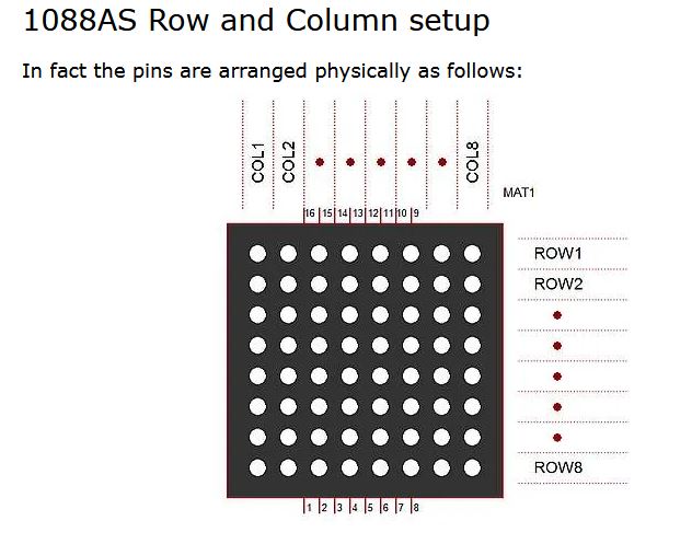
the 8x8 display, using the 3 displays and your code. From left to right. (data in is to the left ). is the hours, min and seconds ( examples ) and from drawing i see on the net that show the pinout of the display. it appears that your code starts the 1st led at ROW1-COL8, then counts up to ROW8-COL5 is that correct ?
If i am looking at things right. would be easier to explain if i was able to show a lil video.. but i can only post pictures..
unless i think wrong (not enough experience) shouldn't the counting start with ROW1-COL1 ? wouldn't this be an easier way to do things when wiring up my clock display ?
and last but least.. Should i wire the leds starting with ROWS 1st ? ROW1 or ROW8. sorry if i seem dumber than i started..
Was easier when i made this thing with the 4017's long ago..
thanks again..
Ok,, update.. Been piddling in the shop while Santa is out on deliveries... Lol
Like they say, learn by doing,, i got my display partially wired up for testing.. It was a big learning curve for me.. But i got it now i think. Leds are counting sequentially 00,01,02,03 etc, and led 59.
I'll probably start on it properly, and hopefully i can report..
How does one go about paying videos on here?
The MAX7219 was designed to drive 7 segment displays. The terminology used in the data sheet is segments and digits of the individual 7 segment displays. When used to drive an 8X8 matrix segments maps to columns and digits map to rows.
When I defined lighting individual leds I mapped the digits to groups of rows and the segments to dots in the row.
LED row dot
0 0 0
1 0 1
2 0 2
.....
7 0 7
8 1 0
9 1 1
...
15 1 7
16 2 0
17 2 1
etc
To find the row for an individual LED divide the LED number by 8. The remainder after dividing by 8 is the dot (col, segment) in the row. Since 8 is a power of 2 the divide and remainder computation can be simple bit operations.
number >> 3 shifts the number 3 bits to the right which is equivalent to dividing by 8
number & 7 turns off all bits except the last 3 and is equivalent to the remainder after dividing by 8
For example 27 = 1B hex = 1 1011 bin
1 1011 >> 3 = 11 or row 3
1 1011 & 111 = 011 or dot 3 (7 = 111 bin)
Different displays can have different mapping of rows and col. The ones I have start in the lower left corner, go across, then to the left side of the next row up. It seem that the one you have maps the col the same but the rows are in reverse order.
Almost every peripheral chip in existence uses some kind of serial interface. So boo hoo as far as the software goes...
Serial interface is great, makes life easier, Why boohoo about software? I'm not complaining.. Trying to learn and understand things.. I'm figuring things out as well..
Like i realized that I'll have to reposition and rewire leds as well..
Before i had the leds in series, but now i'll have to make the minutes and hours in parallel. which means i need to order some resistors now..