I have been looking to build a arduino compatible liquid level sensor based on the change in electrical conductivity (EC) between two platinum electrodes. I have been looking for some schematic online and found this below. I need few clarifications owing to my limited electronics knowledge.
An EC measurement system should have Alternating Current between the electrodes, but this system is powered by DC. How does this supply AC between electrodes?
The component values like resistance values are not suggested in this schematic. Can anyone suggest the correct component values?
I was reading here%20and%20act%20on%20it.) that to get "an" EC value all that one has to do is connect one volt to 5V and the other to analog input via a current limiting resistor, and take the readings. So if we calibrate it we can know how much voltage change happens for unit volume, and then make it predictable? If it is that easy, why the super complicated diagram above?
also @horace , if we switch the digital pin on and off at 10KHz, would that successfully do away with the problem of the ionic migration to electrodes? What if we connected both the electrodes to 5V digital signal and same analog pin and did something like using logic level MOSFETs to switch between circuits (I hope I am clear what I mean). Can we switch MOSFETs at 10KHz?
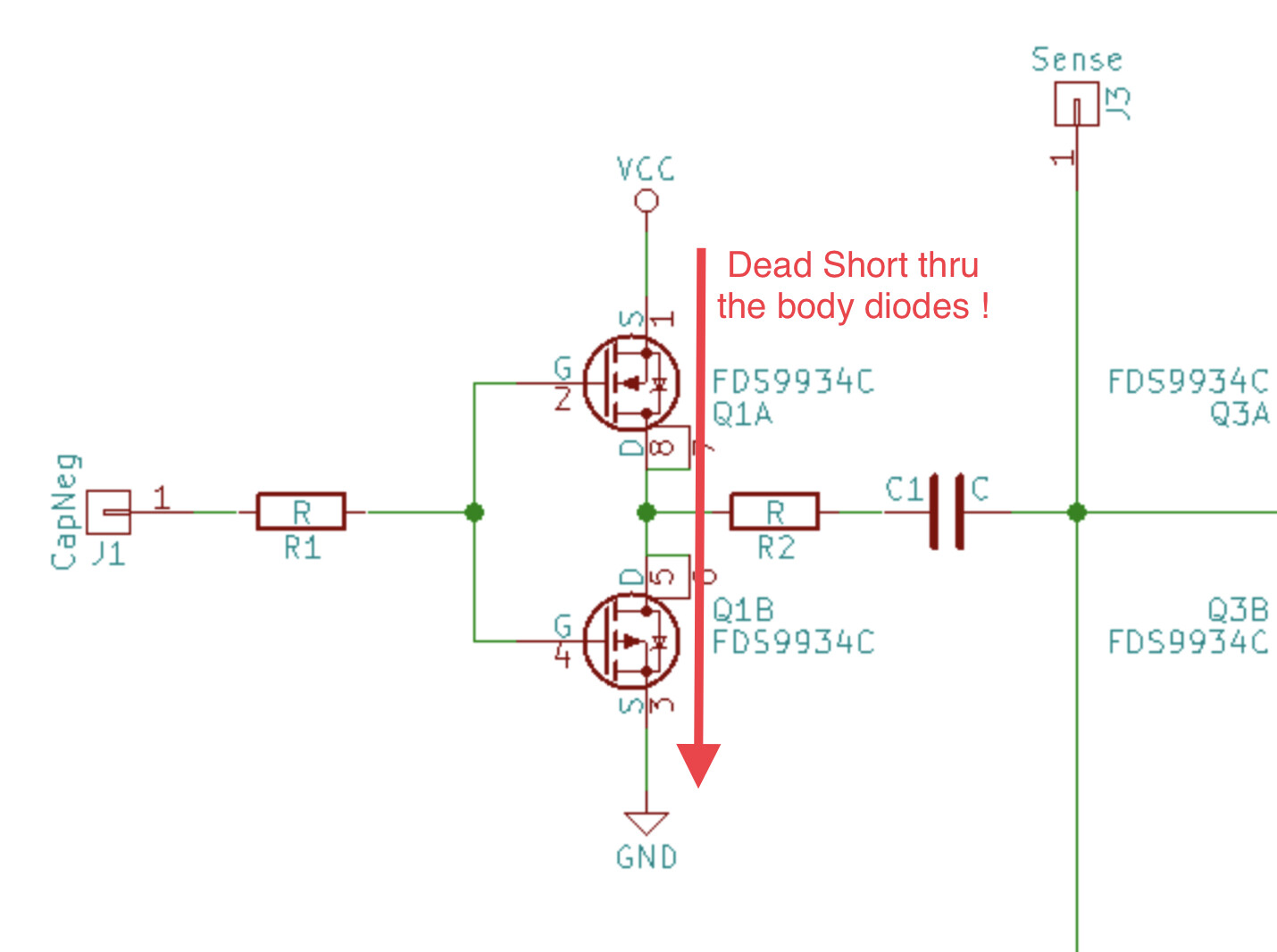
That's a very old schematic of mine! Interesting that it's been found again. It seems the mosfets are the wrong way around I've never actually built this version of the project, it was a design study basically.
Frequency should be 1k-1M Hz, ideally 3-300k, for accurate measurements of the EC.
Note that this is utterly unsuitable for liquid level measurements, as the resistance measured in that case is not just a function of the liquid level, but also of the conductivity of the liquid. There's no way you can get reliable level measurements out of it.
The use of platinum means there is NO chemical activity on the electrodes. So the use of DC is not a problem. The use of AC is to ensure electrodes are eaten away at the same rate for both electrodes.
Not so. DC remains a problem, whether you use platinum, graphite, or other inert materials for electrodes.
The electrodes themselves are not eaten away, however there IS electrolysis going on. Ions in the liquid (those very ions that provide conductivity) move to the electrodes, and almost instantly conductivity as measured between the probes decreases.
That's the main reason you need to use AC for this measurement, it prevents this movement of ions. That your electrodes don't get eaten up is just a nice byproduct.
The ion movement becomes an issue under about 3 kHz, a significant issue under about 1 kHz. Interestingly (I don't know why), the linearity of the measurement ends at about 300 kHz, and becomes significant at about 1 MHz. Those frequencies are or NaCl in water - other ions may behave a little differently. All studies in this that I have seen are done with NaCl, as that's the most common salt found in natural water.
Thanks. I understand what you mean in your earlier comment about the unsuitability of this for level sensor, but I'd still like to try it once. I would be using tap water for this. With no idea about its conductivity, what frequency would you say I should go with? Maybe a 100K? Or 10k?
Depending on the hardness, tap water can have a very low conductivity.
When you do this experiment, add a pinch of salt (kitchen salt or baking soda) and see the water level reading jump Also measuring resistance using AC is anything but trivial. The two methods that I've used are measuring capacitor discharge time (interrupts, counting clock pulses) and oscillator frequency counting (for a specific duration, using the T1 pin as clock input of timer1).