I'll have to dig up the sketch I used, it has been quite a while since I was working on it. There are so many versions!
As far a wiring... I have been taught/I have learned that when you build a system, you use the negative wire as a common return to minimize the number of wires needed. Since using Arduino, though, I have been needing to include transistors and MOSFETS (NPN). This causes a 'reversal' so that the positive now becomes the common and the negative carries the signal. I had wired the ship p to be negative grounding. So then I had to research how to get the polarity reversed using a PNP transistor so I could use It in my model. I never did get it finished before the nacelles fell off, and I have abandoned it (I even did the 4 colour Aztek markings on it) and am rebuilding it with more support for the pylons.
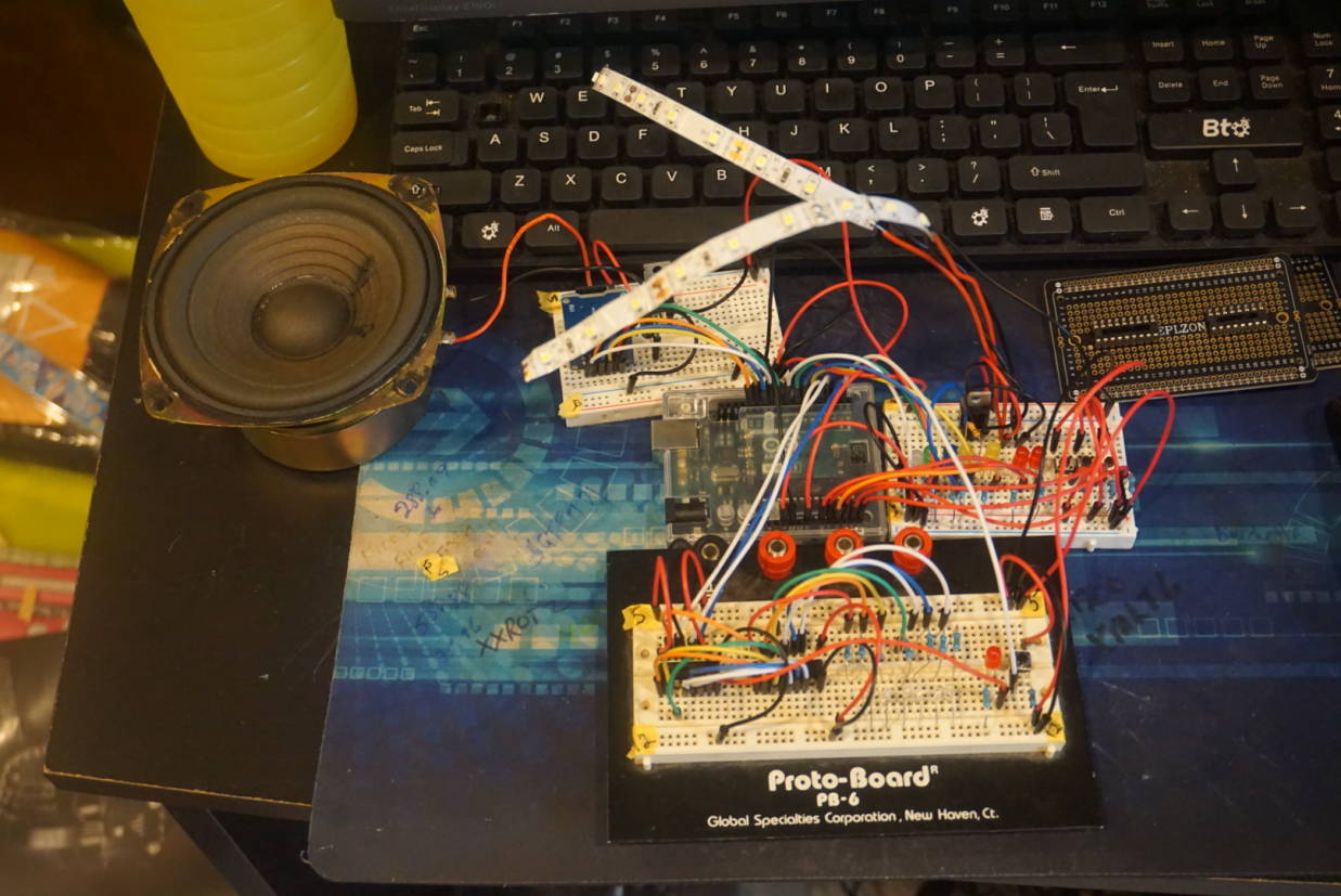
Sorry to the folk who aren't model builders. The Arduino is the next step up from a component system from the 80's, to make our Star Trek models come to life.
I'll find the code that actually worked in prototype.
First, I want to thank everyone for their help and not making feel like I don't know what I'm doing. When it comes to this coding, I really am lost!!!!
As for the electronic part, I do have a degree in electronics and in the Army, I repaired components of few different missile systems along with radios and other electronic equipment. It's just been a long time since I've worked on a project like this and I am having trouble remember even the easiest things.
With that said, about 80% of the project is fixed and working. Yesterday, I figured out what was wrong with the LED's attached to the Darlington chip, THEY ARE ATTACHED BACKWARDS!!!!!!
Instead of the leg with the resistor going to ground, it is going into the Darlington. Stupid me, didn't pay attention when I was wiring up all the LED's and I tied those LED's to ground like normal. There is no way I can separate those LED's from the others since they are all in the closed up model.
So my question is, is there some thing I can use in-between the Darlington and the LED's that will make it work like the set up in the picture????????
As I said, as long as the resistor is part of the path for the current passing through the LED it does not matter where it is in the circuit. It does not even need to be connected to the LED
It's about using a positive common instead of a negative, as the transistors reverse the "flow", so signal comes out on the negative rather than the positive. I had to find an "complimentary" MOSFET or transistor (PNP) to get the voltages back to positive feeds and negative ground. With limited success.
Sir, I just came from my local electronics supply store with no success on a PNP Darlington Array.
Have you seen one or do you have a chip number for a 16 Pin DIP PNP Darlington array.
It might look like I am going to have to build PNP Darlington from scratch and have to add another circuit board to my layout if I can't find one.