Hi all,
I've posted this to project guidance because I'm not sure if there's another more specific section it should go in. I've ordered and finally received a WWVB receiver module from "Canaduino". I ordered this on Amazon, but I believe the seller is affiliated with this Canada-based company. Anyway, a card in the package directed me to go to Universal-solder.ca to find code examples for this module but unfortunately I have not found any. They have a forum that I have not yet attempted to sift through and it looks pretty vacant anyway. I sent an email to the company asking if they had any example code for the module to get me started but unfortunately, they're "Closed for vacation" until July 26th.
Searching the internet I have found a few examples, but I'm not sure if they will work with the specific module I have or not and have not yet had a chance to try anything out. I'm hoping somebody here might have an idea where I can start. Obviously there are plenty of Arduino friendly time-keeping solutions available, but I stumbled across this one while digging up some information for another project that I have since solved and thought it would be a great opportunity to learn how to make use of another technology.
Here's a link to the device I have: WWVB MFS JJY60 Atomic clock receiver module
This receives the 60kHz signal from WWVB in Colorado. I have read a bit about how this works and I'm excited to implement it and see if I can get it working. It includes the large ferite loopstick antenna. As small as this board is, I imagine there's not much filtering being done and I am certain I'm going to have trouble with that where I'm located but I'd like to give it a shot anyway. I've already confirmed I get good copy of the 60kHz station with my Icom HF transceiver and can USUALLY also pick it up using my much older Knight Star-Roamer, which is a superheterodyne tube receiver. It is also using a large loopstick antenna, but obviously a bit more sophisticated (I'm assuming) than the few components on this little board.
So does anybody have any code that I could use to get started? The only related threads I've found here are read only and have gathered significant e-dust, but I'm willing to try them out if it's all there is. Just hoping to find something before the Canadians get back to me at the end of the month.
Thanks in advance, let me know if I've left anything out that would help formulate better input.
Unless you are in an area with good reception, it is quite difficult to deal with WWVB reception errors. In April 2010, Ed Nisley published a good Arduino WWVB receiver article in Circuit Cellar, issue 237, called "The Totally Featureless Clock". It is reported to handle the problem fairly well, but doesn't work well in my area.
You can download the code here.
The code uses a primitive edge-triggered interrupt method to time pulses, and then examines the result for illegal pulse widths. That is very sensitive to noise, and could be vastly improved by continuous sampling, but I haven't got around to it.
And you are receiving the HF frequencies of WWV, NOT the VLF frequency.
Paul
It is receiving WWVB on 60kHz. I have a couple of those antennas/boards and they work as advertised.
Pete
This is a simple bit of test code for the WWVB receiver module. It flashes the LED in sync with the T pin which indicates reception of the pulses. Tested on a NANO but simple enough it ought to work on almost any Arduino/Teensy/etc.
// For a NANO

// WWVB coverage:
// http://tf.nist.gov/stations/wwvbcoverage.htm

/*
  Pinout for universal-solder version is

  Supply voltage range is 3V-5V
  Normal operation has PON connected to ground.
  In standby mode, PON is connected to Vdd
  TCON is the input to WWVB_PIN - no pullup required

V   - Supply voltage +5V
G   - Gnd
P2  - no connection
T   - Time pulse to NANO pin 2 (no pullup)
P1  - HIGH: Rcvr OFF, LOW: RCVR ON. Do not leave floating
      Normally just connect this to ground.
      If this pin is switched from HIGH to LOW it resets the
      receiver.
AON - no connection.


  There are consecutive position markers at the 59th and 0th
  seconds which allow synchronisation.
  The change in the pulse starts exactly on the second
  (unlike WWV which also has a "tick" in all but two seconds).
  A position marker is 0.8s of low power
  A one is 0.5s of low power
  A zero is 0.2s of low power
*/


// TCON is connected to this pin. TCON is the inverted output signal.
#define WWVB_PIN 2

// Flashes in sync with receiver pin
#define LED_PIN LED_BUILTIN

void setup(void)
{
  Serial.begin(9600);
  while(!Serial);

  pinMode(LED_PIN, OUTPUT);

// Don't set the internal pullup
  pinMode(WWVB_PIN, INPUT);

  Serial.println("Start");
}

void loop(void)
{
  if(digitalRead(WWVB_PIN)) {
    digitalWrite(LED_PIN,HIGH);
  } else {
    digitalWrite(LED_PIN,LOW);
  }
}
Reception is best during the evening and night (9pm-6am) but it can still receive during the day. I'm running this code right now (1:55pm) and it is indicating reception but the pulses are often "glitched" which would make decoding difficult until later in the evening when it will start receiving a solid signal.
Pete
In my case, the "glitches" were so frequent that the Nisley code linked above never worked. No entire minute was observed to pass without at least one bad pulse. I do have commercial WWVB clocks in the house that keep perfect time, so it is not a hopeless situation.
I too could see the signal pulses using an LED, (using a simple transistor driver directly from the radio output) so there is no doubt about receiving the proper 60 kHz WWVB signal.
My idea was to implement a 1-second phase locked loop synchronized to the ticks, and then simply poll the input very frequently to determine the pulse width.
I've written code for a Teensy3.2 to decode the WWVB pulses and keep an RTC in sync. It also logs all decodes and has been running for over a year. In March and April the signal was so good in the evening/night that it was decoding each minute's transmission for several consecutive hours.
As I mentioned previously, decoding is best during the night but also the Teensy3.2 circuit is in an upstairs bedroom closet about 15 feet above ground. At the moment (4pm) it is also glitching but not as much as the simple Nano version which is only about 3 feet above ground.
Pete
@el_supremo: How about posting the code? Not much is available.
Thanks for your consideration.
el_supremo:
It is receiving WWVB on 60kHz. I have a couple of those antennas/boards and they work as advertised.
Pete
I meant the poster using an ICOM receiver and and old Star Roamer receiver.
Paul
It'll depend upon which ICOM HF rig. Some recent rigs have receive coverage down to 30kHz.
But you may be right that the OP was actually listening to WWV on HF.
Pete
You've definitely got the right parts steverobey.
Instead of buying new radios, I went to Target and Walmart and bought their cheapest "atomic" clocks. I took them apart, and extracted the parts shown below. (Interestingly, the clocks still worked fine after removal, and are as accurate as any other battery clocks I have.)
I got these:

from clocks like this one, which was $14 from Target I think:

Here is an interesting thread to read: Arduino and atomic clock (WWVB) receiver - Interfacing - Arduino Forum
ps, I've built some wwvb clocks. I like to visualize the 5 kilometer long wave crawling across the mountains, plateaus and valleys between me and Ft. Collins, Colorado where the (huge) WWVB antennae are. It stretches from clinging to the ground, as ultra low frequencies tend to do, all the way to the stratosphere, although it gets a bit thin up there. The science behind the F1 and F2 clocks, which create the data for the stream, is also interesting.
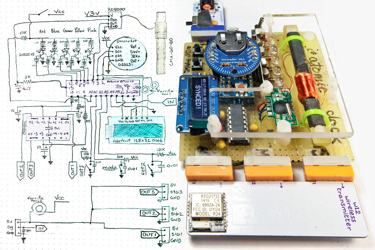
One more picture - here's the schematic and a picture of my first Arduino/WWVB clock, which was also my first "hard" Arduino project, way, way, way back in the day (so forgive my nube mistakes!):

(code for this project is attached)
rtcRadioOledReal4b.ino (19.1 KB)
Regarding what I stated about receiving signals from WWVB on my ham radio gear, Paul, you're right, I'm hearing the HF signals. I had made the assumption that what these WWVB decoder modules were decoding was some carrier in that same signal that is perhaps not audible on the HF signal. I'm probably misunderstanding something there. I live in central/eastern Washington state, for the hams, im just about smack in the center of grid square DN07ic. I wouldn't be above connecting the module temporarily to an inverted V antenna outside after matching with Diawa solid state transmatch just for testing. Obviously at some point I'll want to put the project into an enclosure if i can get it to work reliably though.
Thanks very much Pete for sharing some code and it's great that the top of the code explains the hookup. I'm really disappointed that there wasn't much information or sample code at Universal-Solder.CA but again, I might be looking in the wrong place. Still their fault since they designed their website the way they did. IF they have any example code, I won't likely get a chance to look at any of it before the 26th. Your code, however, will at least get me started. I've read a bit about measuring the duration of pulses to determine from that weather the bit should be a 1 or 0 and storing this in a buffer. Shouldn't be too difficult but code examples do help things along.
From everything I have read so far, my assumption is that an RTC module is still required as the time keeping device once the MCU has decoded. Passing the time update to an RTC is simple if you have the right version of the RTC library (There's an unfortunate number of similarly named libraries for this that are pretty terrible) but that's also something I've already managed to track down. I have an "Extra" RTC module that was really cheap and as such the battery on it is no good, so this project with that module is a good fit in my opinion as the WWVB module will be required to set the clock correctly. As long as the module remains powered after being set, it should keep time just fine.
I suppose if I don't have good luck with the WWVB module, I can utilize other off the shelf solutions until we reach solar maximum for the northern hemisphere. Unfortunately, I'm not going to wait that long. The idea was to manage accurate local time without having to have a human calibrate the RTC and without using NTP since that would require access to the internet, or some other wireless system that keeps time. Maybe the simpler answer is just to use GPS. It's got other obvious applications. That's if nothing goes right with the WWVB module though. I've already got a $15 GPS module that I could use, but I've already played around with that and this is something new for me to try out.
Thanks again and I'll try out the code that's been shared when I get back home.
- KG7WPQ
Hi guys,
I just wanted to add another update since I actually got an email back from admin@universal-solder after my inquiry about any possible example code they might have that just wasn't published well on their website. The guy literally told me to google it. Well I've been googling information on this module pretty much since it arrived in the mail and literally the only useful information I have found came from Arduino.CC and from those of you who have replied to this thread. I'd expect terrible to non-existant support if I had bought this thing from a Chinese vendor, since they rarely care about anything but your money, but ignorantly, I thought this Canadian company would be a little more inclined to offer some support. Stupid me I guess. Anyway, I just thought I would share the bad experience and encourage anybody interested in building a WWVB clock project to just go ahead and scavenge the receiver module from a cheap atomic clock you found at target.
Along with that, come here for technical support.
I'm angry but not discouraged, because I have access to this forum and seem to be getting somewhere. When I come up with additional code based off of what Pete has shared with us, and anybody else who has code they want to share, I'll make sure I paste it here and most definitely NOT in the seller's forum 
-A little salty perhaps
I found some code that might be helpful.
Still searching around to see what others have come up with for this WWVB receiver module so I figured it best to share in this thread. I have not gotten a chance to try the code out yet as I've only just found it and didn't think to plug an arduino into my development computer at home. Sometimes I like to remote into it and tinker around with projects when I have breaks at work. Anyway, the following link will lead you to some code for an "Almost accurate clock" that was referred to on a very short reddit post. Because I like to preserve things like this before they get taken down, I'm going to make a local copy of the code. If you have a little bit of time to read through this code or even to try it out before I have a chance to get to it this weekend, please share any findings here, maybe together we can build up some concise code for this..
'duino lab "Almost accurate clock"
This code is designed for the CMMR-6P-60 but it looks like it can be used with other modules, possibly without modification? and displays information on a 16x2 LCD for date and time, as well as signal quality. I'm also wondering if the guy who wrote this was having problems with spurious emissions as he mentions mounting the antenna away from the rest of the circuit in a window to improve signal. The code also requires that a few jumpers or dip switches be wired up to set your local timezone and DST. I'm starting to visualize something in a project box with a few toggle switches to set this, just because toggle switches would be amusing to use for this.
I'd also like to note that this code doesn't utilize an RTC module, it's just using the MCU clock to keep time between received signals. Obviously it wouldn't be too tricky to add in an RTC with this code. There's already a lot going on, but I think this looks like a really good start.