I have my arduino hooked up to a stepped down voltage "saw" looking DC waveform (~7.5V; all negative voltages chopped off with a diode).
I will post the sketch I have "borrowed" to read the frequency in the serial monitor, but it is not accurate enough, and it seems to really like discrete values (like 60.024 is the value that makes up a large portion of the data), eventhough that is not consitent with what I know AC frequency behavior is, and what my multimiter readout shows it to be.
any help to get a relatively accurate (say to .000 HZ or so) would be greatly appreciated!
Would you please be more specific about "not accurate enough"? Usually the power grid will NOT be exactly 60 Hz. See my grid monitoring experiment Power Grid Monitor | Blinkenlight. The video shows the grid at night. During the day frequency fluctuations are much higher.
I've never used that library, but Google took me here:
Is that the library you're using?
The logic and timing calculation looks basically sound, but I don't quite follow how the periodCount variable is being used. Unless I've missed something, it looks as if it needs to see two complete waves before it will return a result. As long as the waves are consistent from cycle to cycle I think it will probably produce a credible answer, but I wonder whether that's how it's supposed to work.
Have you looked at the numeric resolution within your period/frequency calculation to see whether your '0.024' which is presumed to be a measurement error might be a floating point rounding error?
The theoretical resolution of that frequency counter at 60Hz is 1us/(1sec/60) * 60, which is 0.0036 Hz. So it doesn't explain the 60.024 coming up a lot.
I can see a few things wrong with the frequency counter code that might give you the occasional bogus reading, but nothing in it that explains your results.
If you are using Arduino Uno, the ceramic resonator used for the clock has a tolerance of +/- 0.5%, which equates to 0.3Hz in 60Hz. So a reading of 60.024 might actually be the result of exactly 60Hz input.
When I read your first post, and you need a accuracy of 0.000 Hz ie mHz, I read a magazine article in Elektor about monitor the frequency of the main line to see if it is lower ( lots of power is use on the grid ) or higher ( not much power is use on the grid ).
FWIW, I'd go a different route. If you need a really accurate dedicated pulse counter, I'd hook up the SQW output of an inexpensive RTC to one of the interrupt pins (using DS1307, for example). Then program a 1Hz signal output on the RTC and set up an Arduino interrupt to set a flag or increment a counter for every second that goes by. In the meantime, read the frequency as fast as possible.
Since you don't really need amplitude, you may even do this at a ADC lower resolution, i.e. you can adjust the ADC pre-scaler to a lower value like 16 (vs. the default 128) to get tens of thousands of readings a second. If you want to speed up things further, you can read analog values directly from the relevant port and thus get another reading about every 13 ADC clock cycles (so CPU speed / pre-scaler / 13 = max theoretical sampling rate).
I wouldn't count frequency with an ISR... every time the CPU has to go into ISR mode, you lose 51 CPU clock cycles as I recall. OK if your code has lots of idle time, maybe not so OK if you have time-sensitive stuff going on. Instead, I would dedicate a small period of time (let's say a second out of every minute) to just count the frequency and then dedicate the CPU to other tasks.
RTCs also feature other output frequencies. You could avoid the ISR altogether and do frequency measurements on demand by sampling the frequency signal with the ADC output while sampling the RTC output with a digital input. Since you can sample very quickly using a small pre-scaler, you can set up a for loop that increments every time a RTC signal drops low, then measure a known number of increments at a given frequency to determine your other frequency. Thus, you might be able to determine your frequency with a high degree of accuracy, as needed.
The library you're using is quite simple and it would be very easy to produce your own library which counted multiple cycles to get an average frequency however accurate you want.
I am in Texas, whose electricity grid is isolated from the rest of the US's, and our frequency typically fluctuates between 59.95 and 60.05, with the grid operator purposefully pulsing the frequency above and below 60 with a Generator dispatch algorithm that keeps the dF/dT around zero (on average). When there are large Power plant failures (or simply breaker trips), the frequency can dip as low as 59.80 before the grid can recover to the 60HZ avarage.
My digital Multimeter can measure the frequency to 3 digits past the decimal, so I don't think it would be too much to ask of my little Arduino Mega 2560 to show tic for tic movement out to the third decimal (and not jump around 60.024 59.9875 60.024, etc between readings).
Not sure if the above helps clarify my endeavor and desired accuracy level.
The logic and timing calculation looks basically sound, but I don't quite follow how the periodCount variable is being used. Unless I've missed something, it looks as if it needs to see two complete waves before it will return a result. As long as the waves are consistent from cycle to cycle I think it will probably produce a credible answer, but I wonder whether that's how it's supposed to work.
Have you looked at the numeric resolution within your period/frequency calculation to see whether your '0.024' which is presumed to be a measurement error might be a floating point rounding error?
So I've googled myself blue in the face, and encountered that particular sketch & library, and am using the 4.2 version of it, as I can't get the other one to work right.
A large part of it is that I am new to this and terrible at writing/editing libraries or troubleshooting why this is "not declared" or that is "not defined," or what that even means.
I am in Texas, whose electricity grid is isolated from the rest of the US's, and our frequency typically fluctuates between 59.95 and 60.05, with the grid operator purposefully pulsing the frequency above and below 60 with a Generator dispatch algorithm that keeps the dF/dT around zero (on average). When there are large Power plant failures (or simply breaker trips), the frequency can dip as low as 59.80 before the grid can recover to the 60HZ avarage.
I knew it ! It just like the article/project in the Elektor January 2012 issue...
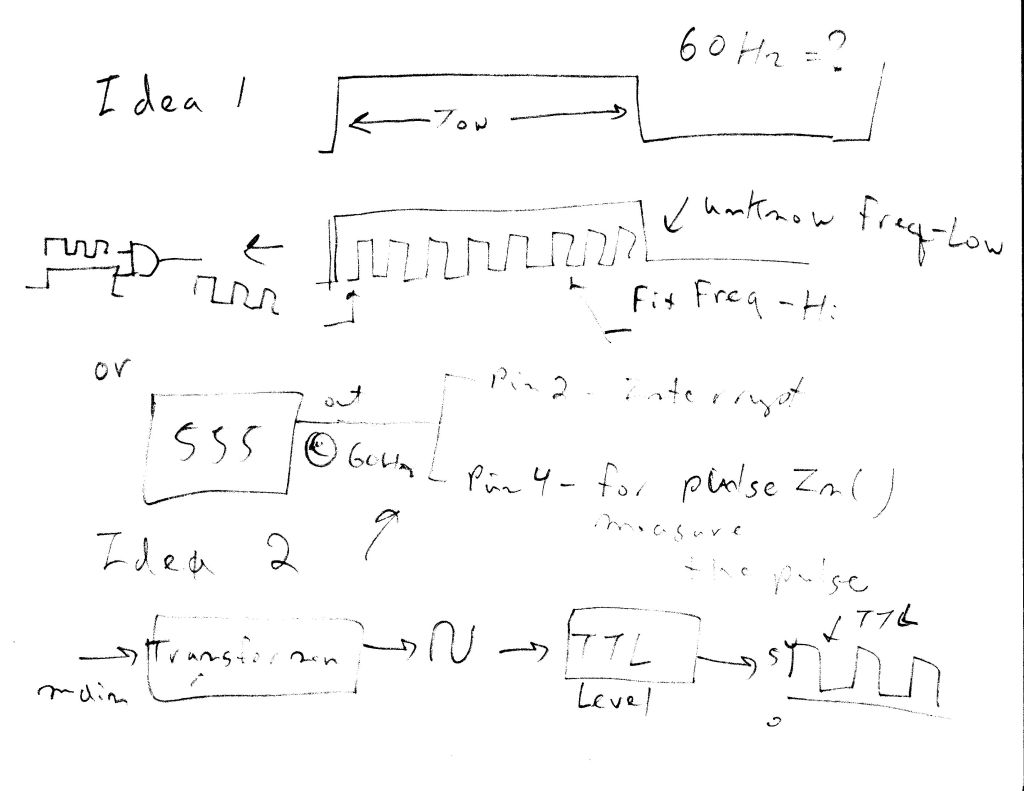
OK let brainstorm here :
Using 1 second time base and count the pulse. 60 pulse = 60 Hz. No accurate enought... you only got 59 or 60 or 61. That it...
Using the Ton of the 60 Hz. T = 1 / F T = 16.667 ms /2 = 8.333 ms 59.5 => 16.806 ms /2 = 8.403 ms 60.5 => 16.528 ms /2 = 8.264 ms hum ? going somewhere here...
Let try the extreme : 59 Hz => 16.949 ms /2 = 8.475 ms ---- 61 Hz => 16.393 ms /2 = 8.196 ms
I hope you see where I am going here... in this case, what about using the Ton for a time base <-- It will vary and a FIX pulse at a higher frequency , let say 100 kHz to 1 MHz. When the fix pulse frequency goes inside the "60" Hz Ton, you just simply "count" the number of fast pulses, when the Ton is lower, the number of fast pulse will be lower, and when Ton is higher, the number of fast pulse will be higher.
After you have the number of pulse counted, you simply calculated for the frequency of the AC frequency being measure.
NOW, that idea will work.. 8) Heh, it is making sense..
I suspect that to get the sort of accuracy you're chasing, you'll need to calibrate the clock on the specific Arduino you're going to use. They don't always run at exactly 16MHz, but do seem to be pretty consistent for a given board.To calibrate it, you could compare clock drift against a known good external clock over an extended period.
If you are measuring the mains frequency by zero-crossing detection then that will have a lot of jitter - there are at least two ways to improve on things.
Measure the period for N cycles - this will give an N-fold improvement (since the jitter doesn't scale with N).
Pass the raw period measurements from each cycle through a simple low-pass IIR digital filter - this averages out many cycles.
(Or even combine the two, use method 1) to initialize the state variable for the IIR filter)
I know it is a lot to swallow at this time. They just idea how to measure a mHz <-- milli Hz , not MHz.
I still prefer my idea. How to impliment the idea... That is another story, maybe a enginner may help you here. Heh , I am just an hobbyiest here. It will come to me...
I already have a pretty simple implementation without any jitter issues: Power Grid Monitor | Blinkenlight. However the display might not be what you expect
I've seen that and it is very cool. I guess you have sort of a led bar meter that moves up and down with frequency.
ultimately I want to feed the data to excel (or something) and aproximate the function over the last "n" measurements (i.e. an ever evolving "best fit" polynomial to the datastream), and then do things with the first and second derivatives of that function.
however, I can't even get a solid and accurate frequency measurement to flow to the serial monitor, so I am having to temper my enthusiasms a little.
I bought a GPS module a little while back, and I think I can get a real accurate time signal from it (to help with my accuracy quest).
I'd still be most grateful for a sample library or sketch to be able to "borrow and edit."
Techone:
2. Using the Ton of the 60 Hz. T = 1 / F T = 16.667 ms /2 = 8.333 ms 59.5 => 16.806 ms /2 = 8.403 ms 60.5 => 16.528 ms /2 = 8.264 ms hum ? going somewhere here...
Let try the extreme : 59 Hz => 16.949 ms /2 = 8.475 ms ---- 61 Hz => 16.393 ms /2 = 8.196 ms
I hope you see where I am going here... in this case, what about using the Ton for a time base <-- It will vary and a FIX pulse at a higher frequency , let say 100 kHz to 1 MHz. When the fix pulse frequency goes inside the "60" Hz Ton, you just simply "count" the number of fast pulses, when the Ton is lower, the number of fast pulse will be lower, and when Ton is higher, the number of fast pulse will be higher.
After you have the number of pulse counted, you simply calculated for the frequency of the AC frequency being measure.
NOW, that idea will work.. 8) Heh, it is making sense..
What do you think...
How (in the sketch) can I implement the above? Sorry that I am such a noob...
To impliment my idea is ... well I am not there yet. I hope you understand what I am talking about, and what I am trying to explain my idea.
I don't know how to impliment ...yet. Maybe external logic circuits ? using the interrupt ? or pulsein() ?
I will be working on it. I have a 555 circuit already build, and I will be using this idea to calculate the RPM. Counting pulses program work, but it is not accurated enought. I have a difference of 10 to 40 depending of the input frequency.
I will try to figure this out. I will draw a diagram to explain my idea better. Maybe someone in this forum will have a better insight to figure my idea out.
Check the Elektor January 2012 , Grid / Frequency Monitor... I will check it out. ( I have that issue )
The problem for both ideas is : Put both signals in "sync" so you can get a measurment. Hardware / software or both ? Hum.. more researches I guess. I will figure it out.
I still think it's easier to use an external RTC to provide a 1s SQW clock signal whose falling or rising edge you can detect easily via an interrupt.
I'd use a smaller pre-scaler on the ADC to speed conversions (you don't need resolution after all) and then detect whenever the voltage curve has gone about halfway above and below the midpoint. That limits jitter. Flip-flop back and forth for a second and you'll know exactly how many times the voltage has shifted from positive to negative. Then divide the results by two and you have your frequency.
If you want to run several seconds to improve accuracy, simply tell the ISR to keep incrementing until you have the right number of seconds in your sample.