Newbie I2C Questions

I understand from the documentation that the GIGA R1 has three I2C buses, and one (I2C2) does not have internal pull-up resistors, which would need to be added externally.

I have many different I2C devices that I am playing with, all of which have pull-up resistors on the SDA and SCL lines. Do these satisfy the requirements of I2C2 bus?
I just want to be sure.

I have also read that if you have too many devices (7+) with pull-up resistors on a bus, you should cut them for reliable operation.
Does an active terminator (i.e. LTC4311) take care of the problem of having a lot of devices on a bus with pull-up resistors?
I would prefer not to physically alter any of them until after I can confirm everything is working first.

Finally, many of my I2C devices are 5V and located up to a half meter away from the GIGA R1.
Is using a 3V to 5V I2C level shifting booster probably sufficient?
Or would a bidirectional isolator be a better option?

Thank you for any advice.

That are a lot of questions, I will try to write a short answer :clown_face:
I have written something about the I2C bus here: How to make a reliable I2C bus · Koepel/How-to-use-the-Arduino-Wire-library Wiki · GitHub

The LTC4311 still needs pullup resistors, because it has to detect the rising signal to be able to amplify the rising signal. It adds an extra 5mA current, which is not according to the I2C standard. It will also amplify noise.
In some special situations, the LTC4311 can be helpful. However, if your I2C bus is so bad that you need a LTC4311, then you should fix the I2C bus first, because the LTC4311 can turn a bad I2C bus into something worse.

According to the I2C standard, the maximum sink current (to pull SDA or SCL low) is 3mA.
That means you can have 9 I2C modules of 3.3V with each a 10k pullup resistor.

A single pullup of 10k should work for testing. For a real project, I prefer to put the sink current between 1mA and 3mA. The total combined pullup resistor can therefor be between 3.3kΩ and 1.1kΩ for a 3.3V I2C bus.
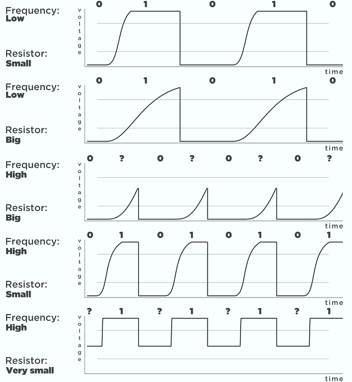
Here are some nice pictures for the rising edge: http://www.gammon.com.au/forum/?id=10896&reply=5#reply5

If you use a level shifter, then it has 10k pullup on the 5V side and 10k pullup on the 3.3V side. A I2C device has to sink all the current from both the 5V side and 3.3V side.

A I2C level shifter can be used to connect a 3.3V I2C bus to a 5V I2C bus, but a I2C level shifter also makes the I2C bus weaker.
If there are two I2C level shifters in the signal path of SDA or SCL, then the I2C bus might no longer work.

Why are many I2C devices half a meter away ?
This is the official I2C standard: https://www.nxp.com/docs/en/user-guide/UM10204.pdf
Read page 54, paragraph 7.5
They give you 10cm for the total length of the I2C bus if you do it wrong.
Suppose that you have ten I2C devices, then each has 1cm length for the I2C bus.
The good news is that if you do it right, the 50cm should be no problem.

Some manufacturers don't put 10k pullup resistors on their modules, they use whatever they have, sometimes as low as 2k2.
Can you give links to all your modules (a link to where you bought them) ? Check all the pullup resistors.

A bidirectional isolator might make things better or make things worse. Which one did you have in mind ?

2 Likes

When you have multiple devices all with pullups, those pullups are effectively in parallel - so the effective pullup value is reduced.

https://www.electronics-tutorials.ws/resistor/res_4.html

If all the pullups are the same value:

  • 2 devices will halve the pullup value
  • 3 devices will give you a third of the value
  • etc, etc, ...

So 7 devices would give you just one seventh of the pullup value - which is quite likely to be far too low!

This picture illustrates the effect of the pullup value:

1 Like

The I2C bus is defined for connections between chip on the same board - so it's really not designed for that sort of distance!

Having said that, you will probably "get away with it" most of the time.

Level shifters for I2C always need to be bidirectional, but isolation shouldn't be needed unless there's other reasons.

1 Like

Yes - the LTC4311 provides all the necessary pull-up current:

Correction:

The LTC4311 does require an external pullup - but a much higher value than would otherwise be needed:

1 Like

Thank you all very much for the feedback.
It is a lot more complicated than I realized.
I started the project playing with an UNO and various I2C devices from Adafruit (Stemma QT), Sparkfun (QWIIC), NCD.io (nodeLynk) and Seeed Studio (Grove).

The final project I2C devices include:

  • 3 Thermocouple Amplifiers
  • 2 Differential Pressure Sensors
  • 2 Air Velocity Sensors
  • 1 Proximity Sensor
  • 2 OLED Displays
  • 2 Isolated 4-20mA Current Loop Transmitters
  • 2 Motor Drivers
  • 2 Fan Controllers
  • 2 Accelerometer / Gyro 6DOF Sensors

A couple more sensors may be added (gas composition & pressure) at a later date.

The distances from the controller relate to local upstream and downstream sensors.

There is also a primary display, user interface, and multiple encoder feedback.

I wanted to eventually move to the GIGA R1 for the 3 separate I2C buses, more memory, more powerful processor, and hoping I might be able to take advantage of the second core and WiFi.

On the UNO I made sure I could utilize each I2C device individually and in small groups, but now I want to put everything together.
Some of the I2C devices were 3.3V for which I used a Adafruit QT 5V to 3V Level Shifter Breakout.
My next step was to try an UNO R4, which I understand will still have 5V logic, but when it wasn't released at the end of May, I picked up a GIGA R1.
I am now adjusting my limited experience to 3.3V logic and how to ensure I2C bus stability.

So I was looking at:

  • Adafruit LTC4311 I2C Extender / Active Terminator
  • Adafruit ISO1540 Bidirectional I2C Isolator
  • Adafruit QT 3V to 5V Level Booster

I was trying to determine if some combination of those components would benefit the setup.
I hope using I2C is ok for this application as it sure makes things a lot easier on the hardware side and all of the vendors seem to tout the viability of their cabled I2C solutions.

Thanks again

Are there motors in your project ? They create a lot of noise, and the I2C bus is a weak bus that picks up noise.

I mentioned in my previous post my thoughts about the LTC4311.

The "Adafruit ISO1540 Bidirectional I2C Isolator" electrically isolates two parts of the circuit. At this moment I don't see why you would need that.

The "Adafruit QT 3V to 5V Level Booster" does not boost the SDA or SCL signal. It has a level shifter, so the SDA and SCL are actually getting a little weaker.

:point_right: If you are looking for ways to "improve" your I2C bus as a precaution, then something is wrong. Your I2C should work optimal in the first place. If there was a way to make the I2C bus better, then the I2C chips would already have implemented that.

There are exceptions. There are for example chips that turn the SDA and SCL signals into twisted pair signals. That is a reliable way to go some distance without disadvantages.

Thank you!
This is an extremely helpful read.
Unfortunately it also looks like a lot of what I have been doing over the last year is less than ideal.
It has given me a lot to think about since I already have most of my I2C devices purchased.

I have two stepper motors.
The project and my introduction to Arduino started with the purchase of an UNO and Grove I2C Motor Driver.
Everything was so easy I just kept adding more devices until I built up a collection of what I needed.
Now it appears I may have been overly optimistic.

As already noted, I2C is not designed for long distances (greater than a few cm) nor for external connections to equipment - using it as such is always going to be "less than ideal".

Late to the discussion, feel free to ignore. Food for thought; you have three options, as I see it.

  • Build it 'as is', see what/if problems develop. Fraught with 'maybe' and 'failure risk', but hey, you might get lucky. Most likely scenario, will work - until it doesn't. Failure is most likely when it's most inconvenient.
  • Segment your design into three parts, looking for modules and data that can be islanded together on each of the three busses to keep the runs shorter. Consider if one or more can be 5V, the other(s) 3.3V, to reduce conversions. Also consider if you can slow some or all of the busses when segmented, as running an I2C bus slower generally improves integrity(but it's not a given, noise is still your enemy). You'll still have only one processor(yay), but you'll be managing three busses, so it will complexify your code somewhat.
  • Extend the segmentation with a goal of having three (or more) processors that exchange data. Experienced members on this forum generally(but not everyone) frown on multi-processor implementations, for good reason, but it might work for you, it's extremely situation and skill-dependent. Each processor will have one short I2C bus, and data sharing between the processors must be designed-in to make this work seamlessly; sharing might be by serial(easier to compartmentalize and debug with Serial Monitor), or RS485(much more robust, overkill in some senses); I have no experience with other approaches. You know your design details, we don't - this may be impossible to do, or it may make sense.
    The third approach will also require that you consider your power environment carefully, as power-up conditions, synchronization challenges, etc. can arise.

I have run I2C in an electrically 'quiet' basement up to 2 meters at the Nano default rate; my app however is much simpler than yours, with fewer devices, and less device variety, so this may be irrelevant. No matter which road you choose, you've got a hill to climb, but only you can choose the hill. My approach would be to choose #2, and migrate to #3 if it becomes evident you're not going to make it, because #2 incorporates the first elements of #3 anyway.

2 Likes

Sometimes, it is said about strong pull-up and weak pull-up; which one is what in the five diagrams of your post #3 (repeated below)?

  • A "strong" pull-up (or down) is one which has a (relatively) high current - so (relatively) low resistance;

  • A "weak" pull-up (or down) is one which has a (relatively) low current - so (relatively) high resistance.

In the diagram, "Small" resistor means low value - so strong pullup

3 Likes

Hi, Hello everyone , do you know how to select a different I2C in the Arduino giga.
Using the wire.h by default is using pins 20 and 21. i like to use the pin 100 and 101 that is also a I2C interfase.

thanks

I noticed a mention of distances for I2C of 10 cm ??? I have been using several devices over a cable up to 3 metres with no significant issues. The cable I use is an ethernet Cat5e which has internal twist "shielding" and works fine..
Regards Colin.

The official standard writes about 10 cm if SDA is next to SCL. It is not something I made up, that is in the official I2C standard. There can be no argument about that.


If SDA is paired with GND and if SCL is paired with GND, and the pullup resistors are low enough so the sink current (maximum current to pull a signal low) is near the 3mA, and perhaps lower the speed, and the GND of the I2C bus is not used for something else (such as motors), and there no voltage level conflict (so the noise margin is fully available), and there are no level shifters (which weaken the signal a little) then 3 meters is possible.

It is very rare that a project meets all those conditions.
When using Arduino Uno boards, then even more is possible because the ATmega328P has a slew rate limiter and input filter and high current outputs. The Arduino Uno can go much further than the 3mA, but then the bus is no longer a I2C bus.