Hi guys so I finally got a Mega 2560 and a MCP2515 & MCP2551 combo board. I cannot seem to get it to work with my Garmin GPSMAP742xs. I tried temperature monitor and looking in the NMEA2000 device list on GPSMAP unit. I also tried Actisense and don't pick up anything.
I have the libraries set up as per the instructions on Github. I do have both the MCP and Due libraries but I don't think that will make a difference. I then also add the line #define USE_MCP_CAN_CLOCK_SET 8 because my MCP board has a 8mhz crystal.
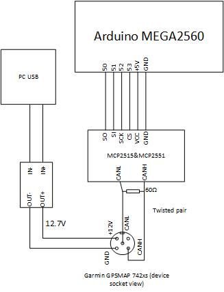
I am adding a rough connection diagram of how I got it wired.
In the cockpit of my boat some analogue B&G displays are installed, but the analogue meters are all broken. I decided to digitize these meters with a tft screen.
I managed to write the program to translate the NMEA0183 messages coming from serial into screen pictures with needle and/or character presentation using a ESP32 (WROVER). I used the NMEA0183 library to parse the messages.
tNMEA0183Msg NMEA0183Msg;
while (NMEA0183.GetMessage(NMEA0183Msg)) {......
Making all ship data available over WiFi was a previous project and is running some years now. For this project I would like to use the WiFi data in stead of Serial data. I wrote a separate program to recieve NMEA messages from WiFi using:
WiFiClient client;
if (client.available())
{
String line = client.readStringUntil('\r');
}
Now I have to combine these programs in order to use the WiFi Stream instead of the Serial Stream. I am using the Arduino IDE for programming so that should not be the biggest problem. But it appears different. The functions used in the NMEA0183 library are specifically writen for receiption through Serial Port.
Please help me by indicating which alterations/extensions should be made in the library or .....?
JCW:
Hi guys so I finally got a Mega 2560 and a MCP2515 & MCP2551 combo board. I cannot seem to get it to work with my Garmin GPSMAP742xs. I tried temperature monitor and looking in the NMEA2000 device list on GPSMAP unit. I also tried Actisense and don't pick up anything.
I have the libraries set up as per the instructions on Github. I do have both the MCP and Due libraries but I don't think that will make a difference. I then also add the line #define USE_MCP_CAN_CLOCK_SET 8 because my MCP board has a 8mhz crystal.
I am adding a rough connection diagram of how I got it wired.
Any help appreciated.
Anyone have some advice for me? I used the MCP2515_Can library to determine that the device initializes correctly over the SPI bus.
There is not much to do. TemperatureMonitor example has been working with Mega. You could also wire int pin and add #define N2k_CAN_INT_PIN xx #define MCP_CAN_RX_BUFFER_SIZE 20 #define USE_MCP_CAN_CLOCK_SET 8 #include <NMEA2000_CAN.h>
...
But I am afraid that it does not help. You need to check wires, powering the bus, terminal resistor connection etc.
Loading different libraries does not make difference. #include <NMEA2000_CAN.h> selects necessary library according to selected processor. So you can have both NMEA2000_mch and _due loaded at same time.
I should move the Arduino connectiong to last and rise Teensy to the top - there is less trouble with it.
Hi guys, I now have two Megas each with a MCP2515 set up. I am having success with the CAN_BUS_Shield-master library.
If I set #define USE_MCP_CAN_CLOCK_SET 8, I have the one Mega run the send example and I can then receive it with the other Mega using receive_check.
If I attach the correct interrupt then receive_interrupt also receives this data.
What would be the next logical step to move over to NMEA2000 to see where things go wrong? I am trying temperature monitor on the one and actisense listener on the other but still no luck. Obviously also setting #define USE_MCP_CAN_CLOCK_SET 8. I tried with interrupt on and off. Nothing.
Yes I followed your whole guide on Git to install the correct libraries. CS pin is correct. And I have both the termination resistors on the MCP modules on. Is it safe to say that since the MCP_CAN library works and I have comms between the two arduinos that the hardware is all good and that I should now look for my mistake in software?
What examples you are using? USE_MCP_CAN_CLOCK_SET definition is on NMEA2000 library NMEA2000_CAN.h module and should not have any effect on CAN examples.
On both samples there is definition const int SPI_CS_PIN = 9; Have you oveeride that? As I mentioned on NMEA2000 library default cs pin is 53. If your cs pin is 9, you have to add definition #define N2k_SPI_CS_PIN 9
before calling NMEA2000_CAN.h
Also check right interupt pin, which is different on "Receive_interrupt"
If I connect the Mega with the actisense listener I get only
CAN device ready
Start address claim for device 0
This tells me that the messages do go pass through from one Mega to the other? I am not receiving anything at all out of the Mega running actisense though. Not even a init message.
If you get 'send failed' most likely you bus is not working. Either tranceiver is broken or misconnected, bus CAN L/H is misconnected or terminal resistor is missing.
Hi guys, this has by far been the most challenging arduino I ever had but I really want it to work.
I did more tests and had some progress. On all these test I made sure my bus resistance is 60ohms and I had messagesender on one board and actisense listener on the other board.
I connected the two Megas to each other via the two MCP2515 boards. I noticed that when I load message sender on one and actisense listener on the other if work ONLY one way around. If I swop the two MCP2515 boards around if does NOT work anymore. When I swop back it works.
While these two are in a working state (receiving messages on actisense listener) I then connect my Garmin 742xs (without termination resistor to the bus). The moment the Garmin device finishes booting the actisense listener no longer receives the messages from the other Mega. When I unplug the +12V from the garmin NMEA2000 connector it works again. So it looks like Garmin unit prevents the bus from working.
I then take a Due wired in exactly the same config as on Timos Git except I use MCP2551 and a voltage divider on the RX to Mega for 3.3V comp. The moment I connect the Due CAN to the but it also stop working.
I then put a termination resistor on the Garmin unit and connect it to each of the Megas individually after uploading message sender to both. Nothing in the device list. Upload temperature monitor to both and try again individually. Nothing.
Update: The Due with MCP2551 works with the Garmin GPSMAP 742xs. I suspect that there is something wrong with these CAN modules. Or likely it is because they are running at 8MHz instead of 16MHz.
MCP2515 controller has been tested by some others with 8MHz and it should work.
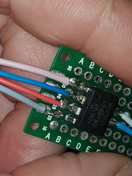
In some pictures you had only modules with megas connected together. Did you had terminal resistor on that test? Modules has jumpers for enabling terminal resistor and at least on picture 20200424_131150 they were not enabled. In that case it may work or may not.
If you are sure and terminal resistors in case 1 then sounds like other module can not send anything. You could connect the module, which worked as actisense listener to bus with Garmin and Due. Then you should see data.
Mega works with another Mega each with a 8MHz CAN module.
Mega with module does NOT work with Garmin
Mega with module does NOT work with Due.
I am convinced there is some compatibility issue with these modules. I read on the web that a lot of guys had problems with 8MHz crystals and some claim that changing to 16MHz solved the problem. I will try and find the posts.
Are you sure you have definition right before including can library?
#define N2k_SPI_CS_PIN 53 // Pin for SPI Can Select #define N2k_CAN_INT_PIN 21 // Use interrupt and it is connected to pin 21 #define USE_MCP_CAN_CLOCK_SET 8 // possible values 8 for 8Mhz and 16 for 16 Mhz clock #include <NMEA2000_CAN.h>