I have bought a nodemcu and a few buttons, I'm trying to get 4 buttons working with INPUT_PULLUP each button has a different GPIO but they all have a common GND. I have tested the setup with the following GPIO's:
{D5, D6, D7, D9}
Other GPIO's are in use for DHT22 and a relay.
The problem is that on the first three buttons work {D5, D6, D7}, the {D9} doesn't seem to function. I have the D9 to a D2 and it remains the same. I can't seem to figure out a reason why it doesn't work.
Is there something wrong? Please help me out on this.
Robin2:
It would probably help if you edit your Original Post and add Nodemcu to the title so that people who are familiar with the device might respond.
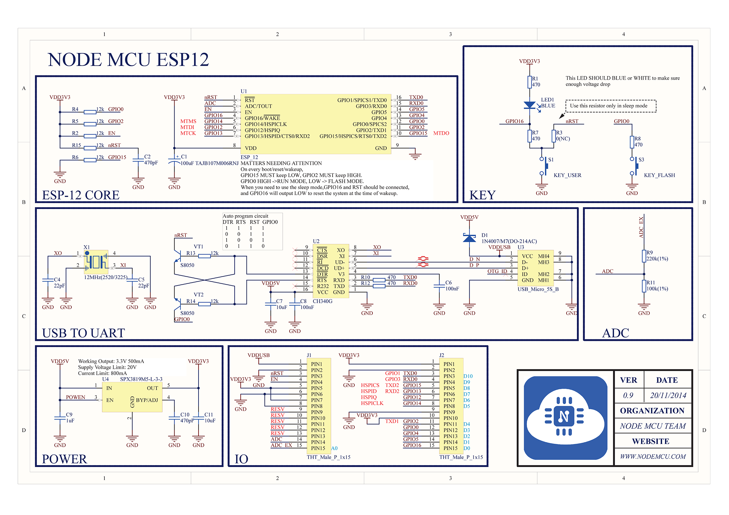
"Rx" is driven also by the USB-Serial device through a fairly low value resistor which would overwhelm the internal pullup. Not clear why D2 isn't working for you.
Well, you start the Serial interface and print to it. I am not familiar with the nodemcu but on many standard Arduinos that would use the Tx and/or Rx pins.
Just out of interest comment out the Serial.begin() line and upload the code
D0/GPIO16 can not be used as input as it's connected to the RESET: pulling it low causes a reset of the processor (which is why you see the LED blink).
Note that this is a NodeMCU specific thing; the bare bones ESP12E/F modules can use that pin as normal input.
D4/GPIO2 is connected to the internal LED (which is lit when the pin is LOW).
D9/GPIO3 is TX (Serial).
D10/GPIO1 is RX (Serial).
The Serial pins can be used as regular I/O pins but then you can't use it for Serial - and of course it may mess up the Serial programming function.
wvmarle:
The Serial pins can be used as regular I/O pins but then you can't use it for Serial - and of course it may mess up the Serial programming function.
Additional notes:
D0/GPIO16 has an internal pull-down resistor (enable it with INPUT_PULLDOWN).
The ADC has a voltage divider attached to it, so its range is 0-3.3V rather than the 0-1.06V the ESP8266 normally has. This divider may mess up an analog signal that itself is also based on a voltage divider!