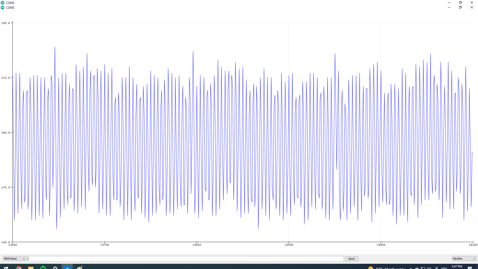
I’m new to Arduino and I’m trying to do a project where I measure my own ECG with an Arduino Uno R3. So far it went well I managed to acquire a not amazing but decent waveform of my ECG. After a week I tried again and I don’t know why but my waveform was full of noise. I will show you 2 pictures of them. The circuit is on a breadboard I remade it with new components and the noise is still there so I don’t think this is the problem, the code is the same for both pictures. If someone could give me a suggestion or an opinion a would greatly appreciate it.
Need to see the sketch and the schematic , how powered etc . If using breadboard , it could well be a bad connection or DuPont wire
Have you changed anything else ?
Or just maybe you need to see a Doctor
Why? Maybe one of the components is defective, or wrong. But you forgot to tell us about the circuit, your construction techniques, the components and the code.
For instructions on how to get help, see the "How to get the best out of the forum" post.
You are always going to get noise with an ECG as the heart is not the only muscle in the region. In general you want to filter some high frequency out. Most ECG machines start with a noisy signal and then start filtering and the signal quality is improved. Of course you need to check your wiring and shielding to make sure you are not picking up EMI. The first ECG seems like normal noise levels
Once worked with an Op over several days on prototype; sometimes the analog stuff would work and sometimes it would not.
Problem turned out that on weekend Op had sunshine for lighting but during the week after work, Op had fluorescent lighting and noise from mercury vapor lighting was creating massive amounts of AC hum.
The first amplifier is an instrumentation amplifier (AD623ANZ) , gain is resistor programmed by RG or more precisely, by whatever impedance appears between Pins 1 and 8. The reference terminal potential defines the zero output voltage and is especially useful when the load does not share a precise ground with the rest of the system. I’m using the other amplifier to provide an offset voltage of 2.5V for the output so it never goes into negative value. The 2 little amp are actually one both powered by the same pin (MCP6002) and I’m using the right amplifier for an active high pass filter in case of unstable voltage level. I wanted to add a notch filter though. I will post the code I’m using aswell. If you need any more information pls tell me and thank you guys for taking your time answearing me. I'm sorry if my english is bad.
const unsigned long INTERVAL= 2;
 unsigned long previousTime = 0;
void setup() {


Serial.begin(9600);
}

void loop() {
  int a=analogRead(A0);
  unsigned long CurentMillis=millis();
   if (CurentMillis - previousTime >= INTERVAL) {

  Serial.println(a);
   previousTime=CurentMillis;
   }


}
Yeah i know, a friend told me that too but it worked and now its showing nothing, looked kinda strange to me. I don't use a shield and i will try to check my wiring again
There is nothing obviously wrong with the circuit (except that no output terminal is identified), but that is not where anyone would expect the noise problem to be.
The noise you show is almost certainly from external sources, caused by breaks in the circuitry, improper grounding and/or improper shielding of low voltage leads and components. This is not a breadboard project!
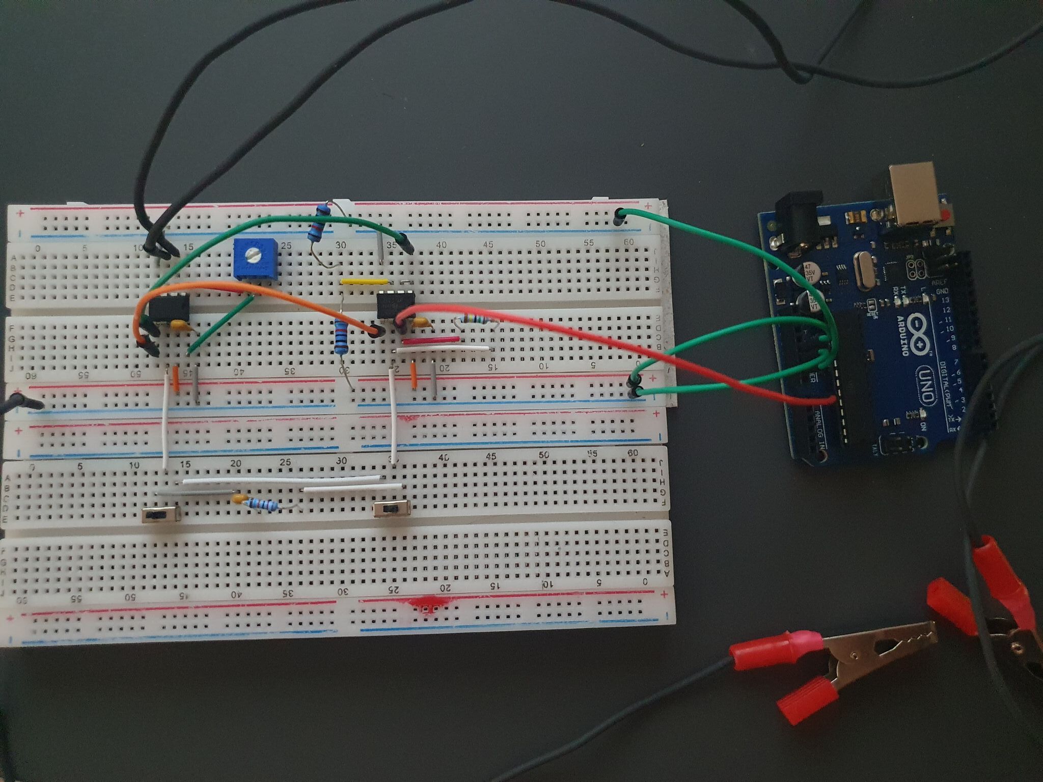
Post a clear, focused picture of your setup, showing how leads are attached to the subject, as well as the rest of the circuitry.
Yeah I know it’s not the best to use a breadboard. I wanted to use ad8232 module but I thought it will be good practice if I don’t use it and try to do something similar.
I hope the 2 photos have decent quality. I forgot to put in my schematic the 2 switches , they are used to activate/deactivate the filter. About the leads placement I can’t do a proper photo but I placed the electrodes on my right wrist , my left wrist and my right ankle (this one attached to the ground) like in the photo I will show. At first I thought maybe the problem it’s the Arduino board but I don’t think that is the issue. Thank you for your reply and your time and I hope this photos help.
Remember that your sensors are big antennae and will pick up your mobile phone and other stuff that is sending data nearby. For instance a wall adapter etc. an oscilloscope could show you the frequency of the interference (assuming emi) and that could help identify it.
The power supply decoupling is greater than your circuit .
Do you gave the gain set too high and it’s just oscillating ? The pot you have is big for the gain you want and therefore insensitive , data sheet gives
“Placing a resistor across the RG terminals sets the gain of the AD8429, which can be calculated by referring to Table 5 or by using the following gain equation:” - see data sheet , values all below 1k.
The layout of you prototyping board may assist giving feed back to the amplifier ( and cause oscillation ) .
Think I would shorten all the signal paths and screen as much of the input path as possible.
The amp is very sensitive to power supply noise , and noise from the Vref circuit could be an issue - be interested to see how it worked on battery ?
You could also try a metal tin connected to 0v placed over the top of the board to screen it .
Do the power supply connections on the prototype board connect all the way along or do they break at the Center ?
Thank you for the data sheet i will look into that. The power supply connections on the breadboard should go all the way along but i will try to verify it. Now that you say it i should have checked it with a battery and i will do that. I will try the metal tin aswell thank you for your suggestions.
The power supply on those type of breadboards do not generally go the whole way, or at least not in my experience. They are broken where the lines are broken and need jumpers. The board is designed to be able to have 4 isolated supplies (or 8 of you don’t join parallel ones). Often there are terminals underneath that allow you to adjust.
It is just about the worst technique, for the low voltages you are trying to measure. Especially under fluorescent lights, all those long wires are antennas to pick up EM noise.
The entire circuit should be inside a grounded metal enclosure.
Shielded RA and LA leads to the body, grounded at the amplifier only, are required.