I am not sure this can be done. I need to read a varying (2-15kHz) frequency. After a manipulation then generate a similar but different frequency in the similar range. Can anyone point me in the right direction or options to research?
use a fast microcontroller (STM32, ESP32, RP2040, etc) using interrupt on change to capture the pulse sequence timing? e.g. have a look at manchester-decoding
Attempting to manipulate a sensor for diagnostic testing purposes my control system is very specific to operation. However, modification of this frequency can cause a slight variation in operation down stream without setting a red flag. My old system used an analog voltage. So adding a small resistor could trick it. My new system uses a frequency generator to monitor the same operation. It may not even work but attempting to try something to see if it is even possible.
Using an Arduino Uno R3 or other Arduino using an ATmega328P.
I have used an interrupt to measure the period of the incoming square wave using micros().
I have used timer 1 to generate the output frequency. Part of the code in setup() generates a continuous square wave on pin 10.
The code in loop() just adjusts the output frequency based on the period measured by the ISR.
const byte inputPin = 2;
const byte outputPin = 10;

volatile unsigned long startTime;
volatile unsigned long lastStartTime;
unsigned long period;

float scalingFactor = 1.1;                                            // multiply input frequency by this factor
unsigned long n = 16000;                                              // initial output frequency 1kHz

void setup() {
  Serial.begin(115200);
  pinMode(inputPin, INPUT_PULLUP);
  pinMode(outputPin, OUTPUT);
  attachInterrupt(digitalPinToInterrupt(inputPin), measurePeriod, RISING);
  Serial.print("Input frequency is multiplied by ");
  Serial.println(scalingFactor);

  TCCR1A = bit (WGM10) | bit (WGM11);                                 // fast PWM,
  TCCR1B = bit (WGM12) | bit (WGM13) | bit (CS10);                    // fast PWM, no prescaler
  OCR1A =  n;                                                         // count n clock cycles
  OCR1B = ((n + 1) / 2) - 1;                                          // 50% duty cycle
  bitSet (TCCR1A, COM1B1);                                            // clear OC1B on compare

}

void loop() {
  n = (period * 16 / scalingFactor);                                  //  calculate new value of n
  OCR1A =  n;
  OCR1B = ((n + 1) / 2) - 1;
  delay(10);
}

unsigned long measurePeriod() {
  startTime = micros();
  noInterrupts();
  period = startTime - lastStartTime;
  lastStartTime = startTime;
  interrupts();
  return period;
}
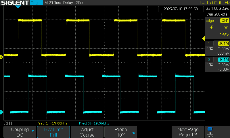
Here are some oscilloscope traces showing the operation:
Channel 1 - yellow trace - input frequency on pin 2.
Channel 3 - blue trace - output frequency from pin 19.
Here is a 15kHz input multiplied by 1.33 to give 20kHz.
jremington,
Thank you for your comments, and the information about interrupts being turned off by default in an ISR.
I think i was getting confused with some other situation where they are necessary.
Thank you for all the feedback. I agree from what I have found as well the Arduino cant do it all. However the LM331 is a very viable option in conjunction with the Arduino.
the LM331 looks interesting
otherwise consider using an ESP32, e.g. to measure frequency and pulse width
// ESP32 - measure pulse width and rising edge-to-edge time using timer1 pins 16 and 17

// updated for Arduino ESP32 core 3.0 see
// https://docs.espressif.com/projects/arduino-esp32/en/latest/api/timer.html

// note using hw_timer_t or micros() give similar values
hw_timer_t *Timer1_Cfg = NULL;  // timer object

// pulse timing data
volatile uint64_t riseTime, period, width;
// rising edge interrupt calculate period uSec
void IRAM_ATTR rising() {
  uint64_t rise = timerReadMicros(Timer1_Cfg);
  period = rise - riseTime;
  riseTime = rise;
}

// falling edge interrupt calculate pulse width uSec
void IRAM_ATTR falling() {
  width = timerReadMicros(Timer1_Cfg) - riseTime;
}

void setup() {
  Serial.begin(115200);
  delay(1000);
  Serial.printf("\n\nESP32 measure pins 16 and 17 pulse information \n");
  //Timer1_Cfg = timerBegin(0, 80, true);           // API 2.x setup timer for 1uSec
  if ((Timer1_Cfg = timerBegin(1000000)) == NULL)  // API 3.0 setup timer for 1uSec
    Serial.println("timerBegin Failed!!");
  Serial.print("timerBegin() OK frequenmcy ");
  Serial.println(timerGetFrequency(Timer1_Cfg));
  //  setup interrput routines - connect signal to pins 16 and 17
  attachInterrupt(digitalPinToGPIONumber(16), rising, RISING);    // detect rising edge on pin 16
  attachInterrupt(digitalPinToGPIONumber(17), falling, FALLING);  // detect falling edge on pin 17
  Serial.println("displaying results");
}

void loop() {
  static unsigned long int timer = millis();
  // if 2 seconds have elapsed since last redaing print results
  if (millis() - timer > 2000) {
    timer += 2000;
    Serial.printf("period %llduSec width = %llduSec  frequency %.2fHz\n",
                  period, width, 1000000.0/period);
  }
}
test results 1Hz to 100KHz
ESP32 measure pins 16 and 17 pulse information
timerBegin() OK frequenmcy 1000000
displaying results
period 10uSec width = 6uSec  frequency 100000.00Hz
period 10uSec width = 4uSec  frequency 100000.00Hz
period 10uSec width = 6uSec  frequency 100000.00Hz
period 100uSec width = 51uSec  frequency 10000.00Hz
period 100uSec width = 52uSec  frequency 10000.00Hz
period 100uSec width = 51uSec  frequency 10000.00Hz
period 10000uSec width = 5000uSec  frequency 100.00Hz
period 10000uSec width = 5000uSec  frequency 100.00Hz
period 100000uSec width = 50000uSec  frequency 10.00Hz
period 100001uSec width = 50001uSec  frequency 10.00Hz
period 100000uSec width = 50000uSec  frequency 10.00Hz
period 999993uSec width = 499995uSec  frequency 1.00Hz
period 999994uSec width = 499997uSec  frequency 1.00Hz
period 999994uSec width = 499994uSec  frequency 1.00Hz
test pulse test frequency 1Hz .01 duty cycle (100uSec width)
period 999992uSec width = 101uSec  frequency 1.00Hz
period 999992uSec width = 99uSec  frequency 1.00Hz
period 999993uSec width = 99uSec  frequency 1.00Hz
period 999990uSec width = 100uSec  frequency 1.00Hz
period 999992uSec width = 98uSec  frequency 1.00Hz
period 999993uSec width = 100uSec  frequency 1.00Hz
period 999993uSec width = 97uSec  frequency 1.00Hz
period 999992uSec width = 99uSec  frequency 1.00Hz
can you give examples of the input frequencies and duty cycles and what output you would generate?
how are you planning to control input to output manipulations? e.g. fixed in code, modified using a potentiometer, modified using a smartphone app, ???
by measuring the input signal period and duty cycle would you generate the output in 'real time'?
output pulses with a different period but same duty cycle
output pulses same period but different duty cycle
output pulses with a different period and different duty cycle
I am attempting to measure a varying input Hz input, lets say 1500 to 6000 range most likely. Idealy the output will be controled by a potentiometer or just hard coded that can be changed. The output would then be generated in real time or even if it is slightly offset should work.