Novice doubts about security and wiring

Hello everyone? How are you? I hope you are doing well, the reason for this post is to share some doubts that I have as a rookie, to try to make my project as functional and safe as possible.
It is related to my previous post, I was making a lot of progress in the hardware and wiring, and I had concerns about some things:
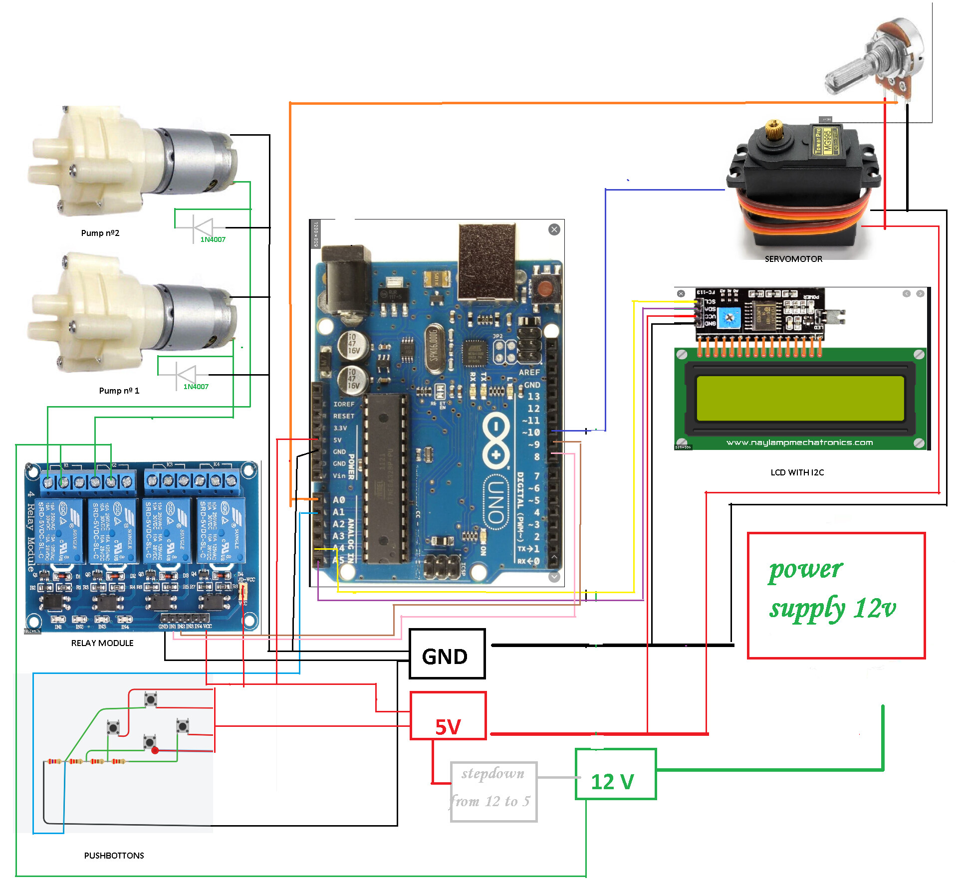
I always see that it refers to that all GNDs have to be tied together, but I ask: they always have to be tied between the same voltages, or when it is said all, are ALL? a voltage regulator and it gives me 5 v .. the masses of 5 and 12 should all be together in a common terminal block or be separated according to their value?

Then I have some "security" doubts, which for example are:
In the 12v and 5v line, place low value fuses as protection, my question is ... in the ground, should it also be a fuse or not? (I don't know if there could be a short circuit in some way, excuse me if the question is very silly or basic)

We move on to the relay part, I have a module with 4 optocoupled relays that are usually used in Arduino, I left the jumper that feeds jd-vcc in its place, since once the voltage regulator outputs 5v, that It feeds me EVERYTHING that has that voltage; I feed the arduino at 5v and gnd (not by usb or by the barrel jack) // to the servomotors, LCD screen, pushbuttons, potentiometer and relay terminal block, now the question is the following :
I read that if I took out the jumper and fed vcc that are "jumpered" that would give me greater security compared to how it is connected now, is that correct?
If the answer is YES, can I do something about it knowing how it is connected and where the power comes from?

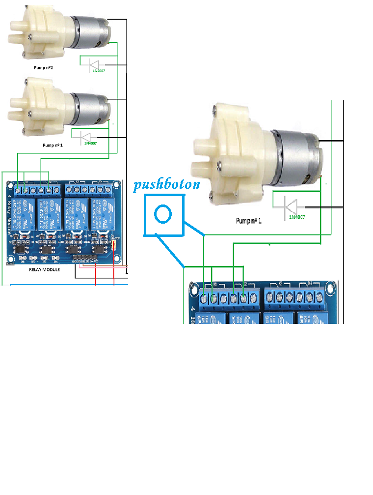
and finally, the relays control r385 diaphragm pumps, which work by programming X amount of time ... but I would also like if you want, by means of a button, to make them work directly ... This would be easily achieved by placing the button between the cable that carries power to the pump and 12v, now my question is: Is this in any way risky for the relays, system or arduino itself? If possible, should I take some precaution, or safety measure?

If you reached the end of the post, thank you very much for reading!

Not.

It sounds like you are saying should you connect the positive 12V and 5V together. Well no no no.

So how are we to know what that was, you should post a link to it if it is important.

Words don’t cut it in electronics we would need to see a diagram of what you are proposing.

I think you are using the word security incorrectly, I would not consider these points to be security issues, but issues of good practice or safety.

I think OP is talking about GND or earth; in Dutch, the word would be massa (if I remember correctly).


Yes, first of all I want to apologize if sometimes I do not express myself well, it turns out that my native language is not English and I usually make mistakes like these; in fact, mass refers to GND or land, here it is known in several ways.
There I uploaded a diagram of what I am mentioning, do not place the push button on the pumps, it is to graph the wiring that I currently have.

Suppose a logic part like a controller and a motor driver, and a motor and the motor power. Then don't t connect motor power gnd to logics gnd if there are 2 different power sources for logic and motor.

Suppose a logic part like a controller and a motor driver, and a motor and the motor power. Then don't t connect motor power gnd to logics gnd if there are 2 different power sources for logic and motor.

let me see if i understand right,i supose in my case the controller and the motordrive is the arduino,the motor are the pumps 12v and the motor power is the power source right?
From this power source,i get 12v to the relay module and to the stepdown and from this last one i get the 5v for everything that use that voltaje...and i MUST NOT connect the gnd wiring from the pump and the stepdown with the gnd from the 5v things?Thats correct?
Sorry for reasquing but i want to be sure before i make something bad.

Too much text. Wiring is the way to go.

My point is that motor driver boards have a + and - for the motor power and a separate, low power side for the logic. They are often galvanically separated using optocouplers. In such a case, don't connector motor gnd to logic gnd.

Okey, I got it. (Late here).
Using one 12 volt power source for both solenoids, motors... and a step down converter giving 5 volt the gnd is of course common. I wrote about using 2 different power sources.
Sometimes the controller, and the driver logics, is powered by f ex USB and the driver motor power comes from a different source. If so, don't connect GNDs.

Hi,

Your diagram is fine, but you really need to draw a schematic of your project showing and labeling all components and pins on devices.
Your diagram shows no information on what the power supply is, what the stepdown regulator is etc.

Thanks.. Tom... :smiley: :+1: :coffee: :australia:

tomgeorge ok,i try to do my best to redraw the wiring and bring more info;
The stepdown is the lm2596s,the power supply is a switiching power 5a 12v.


In the new drawing try to bring the image a little closer, the push button would go between the 12v that go to the relay module and the other leg that would go out to the pump (the pumps are 385r x diaphragm pumps if I did not mention it before)
railroader, no problem, thank you very much for the answer, so I will connect ALL the gnd together, since they come from the same source.

Sorry but you are not drawing a schematic, you have pictures of the components where you should have symbols. Try searching for things like "the schematic symbol for xx", if you don't know what they are. They are much less distracting than the pictures and allow someone looking at the diagram to concentrate on the physical connections.

If you want buttons to override the relays put them across ( in parallel ) with the relay contacts. Remember these have to be able to take the current that the motor draws. You can't use the same type of buttons you used in your analogue connection to the Arduino.

You don't seem to connect the negative output of the regulator, make this your ground. Your diagram shows no ground connections back to the power supply at all.

Also do not connect your pot to the power anywhere near the servo motor, but at your common point or you will pick up interference from the servo motor.

Yes, connect them at one point, this is called star wiring.

Yes, I understand now what you mean by schematic diagram, I will try for the next posts to do it that way to make it easier to read.
The issue of the pushbuttons and their consumption, yes, I had foreseen it ... I just wanted to be sure that "bridging" the relay contacts there was no problem or if it should have any particular consideration.
I accept the error, for trying to modify the drawing as quickly as possible, the gnd that comes out of the regulator could be omitted (All go to a terminal block to which each component is distributed), but the power supply gnd is on the drawing of the regulator , I interpreted that putting a black line would be understood (in fact there is also the drawing of the gnd towards the potentiometer, now I understand what you say that it is not easy to know what the other person is trying to say, I apologize for that)

Thanks for the information on where to connect the potentiometer with respect to the servo, I have written a note that says that to avoid the jigger in the servos you can place a 10uf 25v capacitor + another 0.1 ceramic (104), it also says it has to be as close to the servo as possible .. what do you think about it?

But what you have coming out of the regulator is a black line that then turns to red and is shown going to the +5V point. You only have one connection from the power supplies -Ve output going to the regulator and nowhere else. Now I look carefully at the picture of your regulator you show the output of the regulator being connected to the output of your power supply! The output of the power supply should be connected to the input of the power supply, and the output of the regulator to the 5V and Gnd points. Let's hope that is a fault with your diagram rather than what you have actually done.

Yes this is called power supply decoupling and for a servo I would also include a series inductor like the last diagram in my page about decoupling.
http://www.thebox.myzen.co.uk/Tutorial/De-coupling.html

OK you get this but "consumption" is the wrong word. What you should be using is the word "rating". This means what the switch will handle rather that what it consumes or takes.

Yes, in fact I did not save the changes when I modified the drawing the last time and it was half complete, and I confused the names, I apologize for that, and I also do it in case I sometimes confuse the words, as I mentioned above, English does not It is my native language, and between my knowledge and a little help from the translator when I can't remember the words, those mistakes happen.
Thank you very much for giving me that page, I will read it carefully regarding the inductor (it is the first time that I would use this component, I see that you mention the "henry" scale and say some tens of thousand, it is a scale that I do not know, I will investigate not to buy one that does not serve in the project ..)

Thank you all very much and apologies for the delay in responding.

Fuses. Very misunderstood.

Why do you think you need fuses? Fuses protect the power source- not the device.

No the other way round, one Henry is a very bit unit, not thousands but thousandth of a Henry.
The actual size is not critical, just get the biggest you can get at a reasonable price. The bigger the value the more effect it has.

An induction is the reverse of a capacitor, with a capacitor the effective resistance drops with frequency, with an induction it rises with frequency. So a series resistor looks like a bigger resistor to an AC signal, and just the wire resistance for a DC signal.

This topic was automatically closed 120 days after the last reply. New replies are no longer allowed.