NRF24L01 SPI not connected, transmitter

Hello,

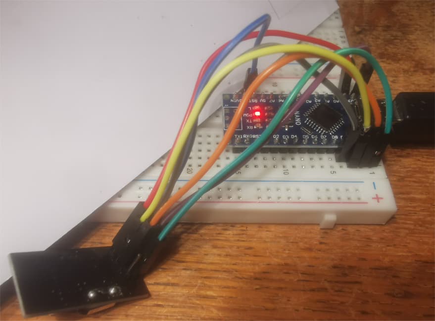
i have a transmitter with a couple of joysticks, the wiring is correct on that one because i used it before and that works.
here is the transmitter code:

#include <SPI.h>
#include <RF24.h>
#include <nRF24L01.h>

#define CE_PIN 7
#define CSN_PIN 6

RF24 radio(CE_PIN, CSN_PIN);
const byte Address[6] = "00001";

const byte joystickPins[] = {A6, A2, A3, A5};
const byte joysticksCount = sizeof joystickPins / sizeof * joystickPins;

struct __attribute__ ((packed)) t_message {
  int16_t rawValues[joysticksCount];
} payload, previousPayload;


void setup() {
  pinMode(10, OUTPUT);
  radio.begin();
  Serial.begin(9600);
  radio.openWritingPipe(Address);
  radio.setPALevel(RF24_PA_MIN);
  radio.stopListening();
}


void loop() {
  // read the joysticks
  for (byte i = 0; i < joysticksCount; i++) {
    payload.rawValues[i] = analogRead(joystickPins[i]);
    payload.rawValues[i] = analogRead(joystickPins[i]) & 0xFFFD; // two reads for stability, dropping the 2 LSb to filter out instability
  }

  // broadcast the data if it has changed
  if (memcmp(&payload, &previousPayload, sizeof(t_message)) != 0) {  // returns 0 when they match, https://cplusplus.com/reference/cstring/memcmp/
    radio.write(&payload, sizeof(payload));
    previousPayload = payload;

for (int i = 0; i < 4; i++) {
 Serial.print(payload.rawValues[i]);
 Serial.print("\t"); }
  }
  Serial.println();
delay(50);
}

this is wired to arduino nano (old bootloader).
when i move the joysticks i get serial data so that should declare that transmitting works.

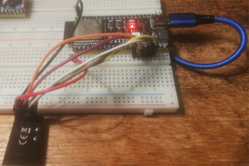
but at my receiving end, wired to an ESP32 S3, i dont get any serial data:

here is the code:

#include <SPI.h>
#include <RF24.h>
#include <nRF24L01.h>


//void begin(int8_t sck =12, int8_t miso =13, int8_t mosi =11, int8_t ss =10);
RF24 radio(10, 9); //CE, CSN
const byte Address[6] = "00001";


// Define the same struct used in the transmitter to store joystick data
struct __attribute__ ((packed)) t_message {
  int16_t rawValues[4];  // Adjust size to match the number of joysticks
} payload;

void setup() {
  Serial.begin(115200);
  
  // Initialize the nRF24L01 module
  radio.begin();
  //SPI.begin(int8_t sck =12, int8_t miso =13, int8_t mosi =11, int8_t ss =10);
  radio.openReadingPipe(0, Address);    // Set the address to listen on
  radio.setPALevel(RF24_PA_MIN);     // Set power level
  radio.startListening();            // Set module to receive mode
}

void loop() {
  // Check if data is available from the transmitter
  if (radio.available()) {
    radio.read(&payload, sizeof(payload));  // Read the data into the payload struct
    
    // Print the joystick data to Serial Monitor
    Serial.println("Joystick Data Received:");
    for (int i = 0; i < 4; i++) {
      Serial.print("Joystick ");
      Serial.print(i + 1);
      Serial.print(": ");
      Serial.println(payload.rawValues[i]);
    }
    Serial.println("--------------");
  }
  
  delay(50);  // Small delay to prevent flooding the Serial Monitor
}

the SPI pin declaration left out was just for testing, i did try it without.

is there anyting i did wrong.
i have the NRF24L01 wired to the 3.3V and GND of my ESP with a 10μF capacitor in parralel, also on my transmittr but then my nano

after adding this in my setup:

    if (radio.isChipConnected())
    Serial.println("Transmitter NF24 connected to SPI");
  else Serial.println("\n\nNF24 is NOT connected to SPI");

for my receiver i get is Connected
but for my transmitter i get is NOT Connected

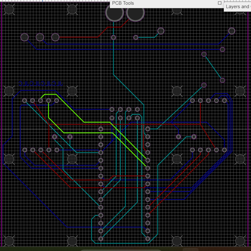
after trying this code from ChatGPT on my transmitter i get the Check wiring message but it is fixed to a PCB so that is strange.

#include <SPI.h>
#include <RF24.h>

#define CE_PIN 7
#define CSN_PIN 6

RF24 radio(CE_PIN, CSN_PIN);

void setup() {
  Serial.begin(115200);
  if (!radio.begin()) {
    Serial.println("nRF24L01 module not responding. Check wiring.");
  } else {
    Serial.println("nRF24L01 module connected successfully!");
  }
}

void loop() {
  // This loop does nothing in this test code
}

but i will charge my 3s Li-ion powering it. because it has been lying untouched for atleast 1.5 years, so that could aslo be an issue. but i didn't think of that because my nano does turn on.

Battery is at 84% so that is not the issue

Since it apparently worked before, I suspect a hardware problem. Could you post an annotated schematic showing exactly how this is wired? Be sure to include all connections, power, ground, power sources, and note any wires over 25 cm (10 inches) in length.

which ESP32S3 module are you using? give a link?
do you always check the radio is connecting to SPI OK?

void setup() {
  Serial.begin(115200);
  delay(1000);
  Serial.println("\n\nESP32_S3 > NRF24L01 Receive text");
  radio.begin();
  if (radio.isChipConnected())
    Serial.println("Receiver NF24 connected to SPI");
  else {
    Serial.println("NF24 is NOT connected to SPI");
    while (1)
      ;
  }

your ESP32S3 code in post 1 does not appear to show this check

if you get the "NF24 is NOT connected to SPI" message it is generally a wiring problem

i double checked the wiring for my transmitter, this is a PCB so that is correct.


4 joysticks, 1 nano, 2 leds and 1 NRF24l0 module. but this worked before. but i just uploaded it to show you guys.

for My esp32 S3 this is the wiring i used, it is already shown in the code itself (not the wiring but pinout)

CE -> 10
CSN -> 9

but i did put these the wrong way around in the code ONE time, can that kill anything?

do you always check the radio is connecting to SPI OK?

i never checked it before, but my receiver NRF module was fresh.

both things use a 3S Li-ion, powering the entire system. and the NRF24L01 modules are hooked up to the 3.3V pins of the arduino and nano. my full schematics of my receiver is a bit big and KIcad also doesn't have all of the components. i also has some other components like: 2 V.reg's ( -> 5&6V) 2 ZK-5AD motor drivers, 4 dc motors, 4 IR-Reflective sensors, 7 always closed pushbutton in parallel, 10 LEDS divided over 3 transistors and a microphone. is this enough info or is it really necessary to 'draw' the full schematics

i dont know how usefull this is but everytime i reset my ESP32S3 i get this in the serial monitor

ESP-ROM:esp32s3-20210327
Build:Mar 27 2021
rst:0x1 (POWERON),boot:0xa (SPI_FAST_FLASH_BOOT)
SPIWP:0xee
mode:DIO, clock div:1
load:0x3fce3818,len:0x109c
load:0x403c9700,len:0x4
load:0x403c9704,len:0xb50
load:0x403cc700,len:0x2fe4
entry 0x403c98ac
Transmitter NF24 connected to SPI

i Just replaced my receiver NRF24l01, just to check if switching the CE and CSN in my code killed it but no, so it really is my Transmitter

my Li-ion batteries are old, i removed them from an old laptop, and given it has been atleast 1.5 more years, they may have worsen even more. but given i don't use that much power i thought it would be fine.

is there a way to "stress test" if my batteries are capable of giving enough power to my nano. i know the NRF24l01 only uses about 13mA but still...

edit 1:

switched it out for a 6 series AA +- 9V same result: NOT connected

nano 3.3V pins gives 3.34V

===============================================
edit 2:

just wired all the connections going to my NRF24l01 parralel to the ones running in the PCB, still the same result: NOT Connected

This type of problem is not usually a power supply issue, but a wiring issue.

If radio.begin() is failing, the MCU and NRF24 are not talking correctly over SPI, so its an SPI issue.
Either your CSN pin is misconfigured, wiring is incorrect, or you have a bad connection/short somewhere in your PCB.

I checked my wiring multible times, it is correct, also in the code. looking at my PCB in EasyEDA, i dont see any shorts (and remeber it used to work just fine, but after touching it it doesnt work). and also with extern wiring from arduino to NRF it still doesnt work.

could it be that my nano is outdated for the library's?

i think what i am going to do, is cut thorugh the 3.3V and GND of the NRF in the PCB and wire a working NRF directly to the arduino itself.
i may look ugly but aleast it will work for now. this is a project for school and i need to get i working asap

Nope, no reason the RF24 library wouldn't work with the nano, no reported issues with any boards. Its a simple SPI communication issue.

then my NRF24L01 is just broken!
but how does that just happen?

looked up some old code to test a Nano with a NRF24L10
Nano receiver

//  Nano > NRF24L01 receiver test using a text string

// UNO/Nano connections
// arduino MOSI pin 11 goes to NRF24L10_pin MOSI
// arduino MISO pin 12 goes to NRF24L10_pin MI
// arduino SCK  pin 13 goes to NRF24L10_pin SCK
// NRF24L10 CE to arduino pin 9
// NRF24L10 CSN to arduino pin10
// NRF24L10 VCC to 3.3V and GND to GND

#include <SPI.h>
#include <RF24.h>

#define CE_PIN 9
#define CSN_PIN 10

bool radioNumber = 1;
const uint8_t pipes[][6] = { "1Node", "2Node" };

RF24 radio(CE_PIN, CSN_PIN);

char dataReceived[10];  // this must match dataToSend in the TX
bool newData = false;

//===========

void setup() {
  Serial.begin(115200);
  delay(1000);
  Serial.println("Nano > NRF24L01 Receive text");
  radio.begin();
  if (radio.isChipConnected())
    Serial.println("Receiver NF24 connected to SPI");
  else {
    Serial.println("NF24 is NOT connected to SPI");
    while (1)
      ;
  }
  radio.setChannel(125);
  radio.setDataRate(RF24_1MBPS);
  //radio.setDataRate(RF24_250KBPS);
  radio.printDetails();
  if (!radioNumber) {
    radio.openWritingPipe(pipes[0]);
    radio.openReadingPipe(1, pipes[1]);
  } else {
    radio.openWritingPipe(pipes[1]);
    radio.openReadingPipe(1, pipes[0]);
  }
  radio.startListening();
  // radio.setPayloadSize(sizeof(Struct1));
}

//=============

void loop() {
  if (radio.available()) {
    char testString[10] = "";
    radio.read(testString, sizeof(testString));
    Serial.print("Test string:      ");
    Serial.println(testString);
  }
}

ESP8266 transmitter

//  ESP32 > NRF24L01 transmitter test using a text string

// RP2040 connections
// RP2040 SPIO_SCK pin GP18 goes to NRF24L10_pin SCK
// RP2040 SPIO_RX pin GP16 goes to NRF24L10_pin MISO
// RP2040 SPIO_TX pin GP19 goes to NRF24L10_pin MOSI
// RP2040 pin SPIO_CSn GP17 to NRF24L10 CSN
// RP2040 pin GP20 to NRF24L10 CE
// RP2040 GND and 3.3V to NRF24L10  GND and VCC

// Leonardo connections ???
// Leonardo ICSP SCK  pin 15 to NRF24L10_pin SCK
// Leonardo ICSP MISO pin 14 to NRF24L10_pin MISO
// Leonardo ICSP MOSI pin 16 to NRF24L10_pin MOSI
// Leonardo pin 10 to NRF24L10 CSN
// Leonardo pin 9  to NRF24L10 CE
// Leonardo GND and 3.3V to NRF24L10  GND and VCC

// ESP8266 connections
// ESP8266 SCK pin GPIO14 goes to NRF24L10_pin SCK
// ESP8266 MISO pin GPIO12 goes to NRF24L10_pin MI
// ESP8266 MOSI pin GPIO13 goes to NRF24L10_pin MO
// NRF24L10 CE to ESP8266 pin GPIO4
// NRF24L10 CSN to ESP8266 pin GPIO5

#include <SPI.h>
#include "RF24.h"

#define CE_PIN 4
#define CSN_PIN 5

bool radioNumber = 0;
RF24 radio(CE_PIN, CSN_PIN);

byte addresses[][6] = { "1Node", "2Node" };

void setup() {
  Serial.begin(115200);
  delay(2000);
  Serial.println("\n\nESP8266 > NRF24L01 transmit text");
  radio.begin();
  if (radio.isChipConnected())
    Serial.println("Transmitter NF24 connected to SPI");
  else {
    Serial.println("NF24 is NOT connected to SPI");
    while (1)
      ;
  }
  radio.setChannel(125);
  radio.setPALevel(RF24_PA_MIN);
  radio.powerUp();
  radio.setDataRate(RF24_1MBPS);
  //radio.setDataRate(RF24_250KBPS);
  if (radioNumber) {
    radio.openWritingPipe(addresses[1]);
    radio.openReadingPipe(1, addresses[0]);
  } else {
    radio.openWritingPipe(addresses[0]);
    radio.openReadingPipe(1, addresses[1]);
  }
  radio.stopListening();
  //radio.setPayloadSize(sizeof(Struct1));
}

// loop transmiting data packet
void loop() {
  static char testString[10] = "text 0";
  radio.write(testString, sizeof(testString));
  Serial.print("transmit ");
  Serial.println(testString);
  delay(1000);
  testString[5]++;
}

ESP8266 transmitter displays

ESP8266 > NRF24L01 transmit text
Transmitter NF24 connected to SPI
transmit text 0
transmit text 1
transmit text 2
transmit text 3
transmit text 4
transmit text 5
transmit text 6
transmit text 7
transmit text 8
transmit text 9
transmit text :
transmit text ;
transmit text <
transmit text =
transmit text >

Nano receiver displays

Nano > NRF24L01 Receive text
Receiver NF24 connected to SPI
Test string:      text 0
Test string:      text 1
Test string:      text 2
Test string:      text 3
Test string:      text 4
Test string:      text 5
Test string:      text 6
Test string:      text 7
Test string:      text 8
Test string:      text 9
Test string:      text :
Test string:      text ;
Test string:      text <
Test string:      text =
Test string:      text >

photo

I will test that tomorrow, thank you.

Power Stability Issues with RF24 Radio Modules

As described in the RF24 Common Issues Guide, radio modules, especially the PA+LNA versions, are highly reliant on a stable power source. The 3.3V output from Arduino is not stable enough for these modules in many applications. While they may work with an inadequate power supply, you may experience lost packets or reduced reception compared to modules powered by a more stable source.

Symptoms of Power Issues:

  • Radio module performance may improve when touched, indicating power stability issues.
  • These issues are often caused by the absence of a capacitor, a common cost-saving omission by some manufacturers.

Temporary Patch :

  • Add Capacitors: Place capacitors close to the VCC and GND pins of the radio module. A 10uF capacitor is usually sufficient, but the exact value can depend on your circuit layout.
  • Use Low ESR Capacitors: Capacitors with low Equivalent Series Resistance (ESR) are recommended, as they provide better power stability and performance.

Adding the appropriate capacitors can greatly improve the reliability of your RF24 module by ensuring a stable power supply, thus minimizing packet loss and enhancing overall performance. A separate power supply for the radios is the best solution.

Sorry I do not have the time to trace your PCB wiring without a schematic, how would I know what is what?

1 Like

updated Nano transmitter and ESP32-S3-DevKitC-1 receiver using your pinouts
Nano transmitter

// Nano > NRF24L01 transmitter test using a text string

// UNO/Nano connections
// arduino MOSI pin 11 goes to NRF24L10_pin MOSI
// arduino MISO pin 12 goes to NRF24L10_pin MI
// arduino SCK  pin 13 goes to NRF24L10_pin SCK
// NRF24L10 CE to arduino pin 7
// NRF24L10 CSN to arduino pin6
// NRF24L10 VCC to 3.3V and GND to GND

#include <SPI.h>
#include "RF24.h"

#define CE_PIN 7
#define CSN_PIN 6

bool radioNumber = 0;
RF24 radio(CE_PIN, CSN_PIN);

byte addresses[][6] = { "1Node", "2Node" };

void setup() {
  Serial.begin(115200);
  delay(2000);
  Serial.println("\n\nNano > NRF24L01 transmit text");
  radio.begin();
  if (radio.isChipConnected())
    Serial.println("Transmitter NF24 connected to SPI");
  else {
    Serial.println("NF24 is NOT connected to SPI");
    while (1)
      ;
  }
  radio.setChannel(125);
  radio.setPALevel(RF24_PA_MIN);
  radio.powerUp();
  radio.setDataRate(RF24_1MBPS);
  //radio.setDataRate(RF24_250KBPS);
  if (radioNumber) {
    radio.openWritingPipe(addresses[1]);
    radio.openReadingPipe(1, addresses[0]);
  } else {
    radio.openWritingPipe(addresses[0]);
    radio.openReadingPipe(1, addresses[1]);
  }
  radio.stopListening();
  //radio.setPayloadSize(sizeof(Struct1));
}

// loop transmiting data packet
void loop() {
  static char testString[10] = "text 0";
  radio.write(testString, sizeof(testString));
  Serial.print("transmit ");
  Serial.println(testString);
  delay(1000);
  testString[5]++;
}

ESP32S3 receiver

//  ESP32S3 > NRF24L01 receiver test using a text string

// UNO/Nano connections
// arduino SCK pin 11 goes to NRF24L10_pin MOSI
// arduino MISO pin 12 goes to NRF24L10_pin MI
// arduino MOSI pin 13 goes to NRF24L10_pin SCK
// NRF24L10 CE to arduino pin 9
// NRF24L10 CSN to arduino pin10

// ESP32 connections
// ESP32 SCK pin GPIO18 goes to NRF24L10_pin SCK
// ESP32 MISO pin GPIO19 goes to NRF24L10_pin MI
// ESP32 MOSI pin GPIO23 goes to NRF24L10_pin MO
// NRF24L10 CE to ESP32 pin GPIO4
// NRF24L10 CSN to ESP32 pin GPIO 5

// ESP32_S3_DevKit_1 connections
// ESP32_S3 SCK pin GPIO12  to NRF24L10_pin SCK
// ESP32_S3 MISO pin GPIO13  to NRF24L10_pin MISO
// ESP32_S3 MOSI pin GPIO11  to NRF24L10_pin MOSI
// ESP32_S3 pin GPIO10   to NRF24L10 CE
// ESP32_S3 pin GPIO9 to NRF24L10 CSN

#include <SPI.h>
#include <RF24.h>

#define CE_PIN 10
#define CSN_PIN 9

bool radioNumber = 1;
const uint8_t pipes[][6] = { "1Node", "2Node" };

RF24 radio(CE_PIN, CSN_PIN);

char dataReceived[10];  // this must match dataToSend in the TX
bool newData = false;

//===========

void setup() {
  Serial.begin(115200);
  delay(1000);
  Serial.println("\n\nESP32_S3 > NRF24L01 Receive text");
  radio.begin();
  if (radio.isChipConnected())
    Serial.println("Receiver NF24 connected to SPI");
  else {
    Serial.println("NF24 is NOT connected to SPI");
    while (1)
      ;
  }
  radio.setChannel(125);
  radio.setDataRate(RF24_1MBPS);
  //radio.setDataRate(RF24_250KBPS);
  radio.printDetails();
  if (!radioNumber) {
    radio.openWritingPipe(pipes[0]);
    radio.openReadingPipe(1, pipes[1]);
  } else {
    radio.openWritingPipe(pipes[1]);
    radio.openReadingPipe(1, pipes[0]);
  }
  radio.startListening();
  // radio.setPayloadSize(sizeof(Struct1));
}

//=============

void loop() {
  if (radio.available()) {
    char testString[10] = "";
    radio.read(testString, sizeof(testString));
    Serial.print("Test string:      ");
    Serial.println(testString);
  }
}

Nano serial output

Nano > NRF24L01 transmit text
Transmitter NF24 connected to SPI
transmit text 0
transmit text 1
transmit text 2
transmit text 3
transmit text 4
transmit text 5
transmit text 6
transmit text 7
transmit text 8
transmit text 9
transmit text :
transmit text ;
transmit text <
transmit text =
transmit text >
transmit text ?
transmit text @
transmit text A

ESP32S3 receiver (start few seconds after transmitter

ESP32_S3 > NRF24L01 Receive text
Receiver NF24 connected to SPI
SPI Speedz	= 10 Mhz
STATUS		= 0x0e RX_DR=0 TX_DS=0 MAX_RT=0 RX_P_NO=7 TX_FULL=0
RX_ADDR_P0-1	= 0xe7e7e7e7e7 0xc2c2c2c2c2
RX_ADDR_P2-5	= 0xc3 0xc4 0xc5 0xc6
TX_ADDR		= 0xe7e7e7e7e7
RX_PW_P0-6	= 0x20 0x20 0x20 0x20 0x20 0x20
EN_AA		= 0x3f
EN_RXADDR	= 0x03
RF_CH		= 0x7d
RF_SETUP	= 0x07
CONFIG		= 0x0e
DYNPD/FEATURE	= 0x00 0x00
Data Rate	= 1 MBPS
Model		= nRF24L01+
CRC Length	= 16 bits
PA Power	= PA_MAX
ARC		= 0
Test string:      text =
Test string:      text >
Test string:      text ?
Test string:      text @
Test string:      text A
Test string:      text B
Test string:      text C
Test string:      text D
Test string:      text E
Test string:      text F
Test string:      text G
Test string:      text H
Test string:      text I
Test string:      text J
Test string:      text K
Test string:      text L

nano photo

ESP32S3 photo

A separate power supply for the radios is the best solution.

i see that now, back then i didn't have that knowledge. but after working on this again i noticed multiple things that can be improved, when the time (and money) comes that i will need this again i will design a good, high quality transmitter suitable for many project, with suffiecient power for all systems.

but right now this is what i have to work with because it is for school and i dont have the time to upgrade.

this is how i have it right now:

on the right you can still see my old NRF24L01 with antenna removed (because i don't need that anymore)
and i got the message Transmitter is connected

1 Like

This topic was automatically closed 180 days after the last reply. New replies are no longer allowed.