Has anyone successfully used an nRF24L01+ 2.4ghz transiever with an Attiny841?
I am attempting to make a wireless node using those 2 main components on a board I made up. I cannot get them to work. I've made multiple boards and tried a few different RF24 transievers with no luck. My master board is not getting any reply.
I am using the SpenceKonde Attiny core - GitHub - SpenceKonde/ATTinyCore: Arduino core for ATtiny 1634, 828, x313, x4, x41, x5, x61, x7 and x8
And the tmrh20 NRF24 library - http://tmrh20.github.io/RF24/index.html
My Master Code
#include <SPI.h>
#include <nRF24L01.h>
#include <RF24.h>

#define CE_PIN 9
#define CSN_PIN 8

#define reedSwitchStatusBit (1 << 0)
#define batteryLowAlarmBit (1 << 1)

uint8_t masterAddress;
uint8_t nodeAddressIndex = 0;
const byte numberNodes = 2;
const byte nodeAddress[numberNodes][5] = {{'R','x','A','A','A'},
                                          {'R','x','A','A','B'}};

RF24 radio(CE_PIN, CSN_PIN); // Create a Radio

bool newData = 0;
uint16_t nodeDataWord[20];
bool nodeCommStatus[20];    //0 = communication failure, 1 = ok

unsigned long currentMillis;
unsigned long prevMillis = 0;
unsigned long txIntervalMillis = 2000; // send once per second

void setup() {
  Serial.begin(9600);
  Serial.println("Home Security Wireless Master");
  Serial.println("Version 1, 04AUG18");
  radio.begin();
  radio.setDataRate( RF24_250KBPS );
  radio.enableAckPayload();
  radio.setRetries(3,5); // delay, count

  masterAddress = 255;
  Serial.println("setup complete");
}

void loop() {
  currentMillis = millis();
  if ((currentMillis - prevMillis) >= txIntervalMillis)
    requestNodeUpdate();
}

void requestNodeUpdate() {
  Serial.print("Request for update from node ");
  Serial.println(nodeAddressIndex + 1);
  radio.openWritingPipe(nodeAddress[nodeAddressIndex]);
  uint16_t radioWrite;
  radioWrite = masterAddress;
  radioWrite |= ((uint16_t(nodeAddressIndex) + 1) << 8);
  nodeCommStatus[nodeAddressIndex] = radio.write(&radioWrite,sizeof(radioWrite));

  if (nodeCommStatus[nodeAddressIndex]) {
    if (radio.isAckPayloadAvailable()) {
      radio.read(&nodeDataWord[nodeAddressIndex], sizeof(nodeDataWord[nodeAddressIndex]));
      newData = 1;
    }
    else {
      Serial.println("Reply From Node But No Data");
    }
  }
  else {
    Serial.println("No Reply From Node");
  }
  showData();
  nodeAddressIndex += 1;
  if ((nodeAddressIndex + 1) > numberNodes)
    nodeAddressIndex = 0;
  prevMillis = millis();
}

void showData() {
  if (newData) {
    Serial.print("Reply From Node ");
    Serial.print((nodeAddressIndex + 1));
    Serial.print(", ");
    Serial.println(nodeDataWord[nodeAddressIndex]);
    newData = 0;
    }
}
My wireless node code
#include <SPI.h>
#include <nRF24L01.h>
#include <RF24.h>

#define CE_PIN 3        //attiny841 pin 6, PA7, digital pin 3
#define CSN_PIN 2      //attiny841 pin 5, PB2, digital pin 2

uint8_t reedSwitchInput = 7;        //Reed Switch Input, attiny841 pin 10, PA3, digital pin 7
uint8_t heartbeatOutput = 10;       //Heartbeat Output, attiny841 pin 13, PA0, digital pin 10

#define reedSwitchStatusBit (1 << 0)

const byte thisNodeAddress[5] = {'R','x','A','A','B'};

RF24 radio(CE_PIN, CSN_PIN); // Create a Radio

uint16_t nodeDataWord = 0;

uint32_t previousMillis = 0;

void setup() {
//  Serial.begin(9600);
//  Serial.println("Home Security Wireless Node");
//  Serial.println("Attiny841, 8MHz, 3.3v");
//  Serial.println("Version 1, 04AUG2018");
  pinMode(reedSwitchInput, INPUT);
  pinMode(heartbeatOutput, OUTPUT);
  digitalWrite(heartbeatOutput, HIGH);

  radio.begin();
  radio.setDataRate( RF24_250KBPS );
  radio.openReadingPipe(1, thisNodeAddress);
  radio.enableAckPayload();
  radio.writeAckPayload(1,&nodeDataWord,sizeof(nodeDataWord)); // pre-load data
  radio.startListening();

//  Serial.println("setup complete");
}

void reedswitch() {
  bool reedSwitchState = digitalRead(reedSwitchInput);
  if (reedSwitchState)
    nodeDataWord |= reedSwitchStatusBit;
  else
    nodeDataWord &= ~reedSwitchStatusBit;

  radio.writeAckPayload(1,&nodeDataWord,sizeof(nodeDataWord)); // pre-load data
}

void updatePayload() {
  radio.writeAckPayload(1,&nodeDataWord,sizeof(nodeDataWord)); // pre-load data
}

void heartbeat() {
  uint32_t currentMillis = millis();

  if ((currentMillis - previousMillis) >= 2000) {
    previousMillis = currentMillis;
    bool currentState = digitalRead(heartbeatOutput);
    if (currentState)
      digitalWrite(heartbeatOutput, LOW);
    else
      digitalWrite(heartbeatOutput, HIGH);
  }
}

void getData() {
  if (radio.available()) {
    uint16_t radioRead;
    radio.read(&radioRead,sizeof(radioRead));
  }
}

void loop() {
  reedswitch();
  heartbeat();
  updatePayload();
  getData();
}
Pins to pins are as follows
nRF24L01+ - Attiny841
1 (GND)
2 (3.3v)
3 (CE) - Pin 6, PA7, Digital Pin 3
4 (CSN) - Pin 5, PB2, Digital Pin 2
5 (SCK) - Pin 9, PA4, Digital Pin 6, SCK
6 (MOSI) - Pin 7, PA6, Digital Pin 4, MOSI
7 (MISO) - Pin 8, PA5, Digital Pin 5, MISO
8 (IRQ) - Pin 3, PB1, Digital Pin 1, INT0
I thought it would be because of digital pin 3 being the default SS for the SPI, and I am using digital pin 2. I used wire jumpers and swapped them around but still no luck. I also tried changing what pin was defined as SS in pins_arduino.h (under tinymodern folder in the hardware directory). Changed it from 3 to 2. Still no luck.
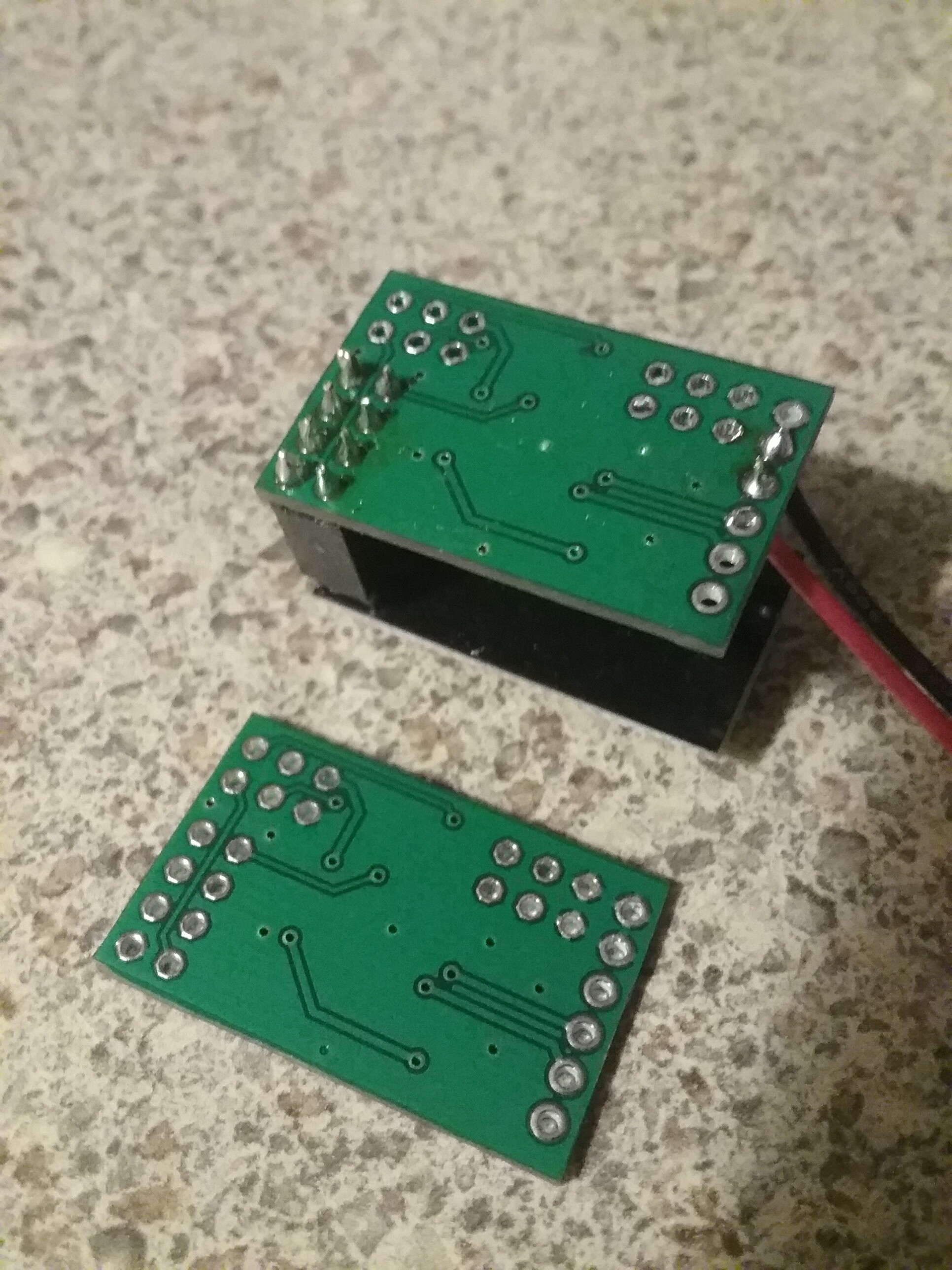
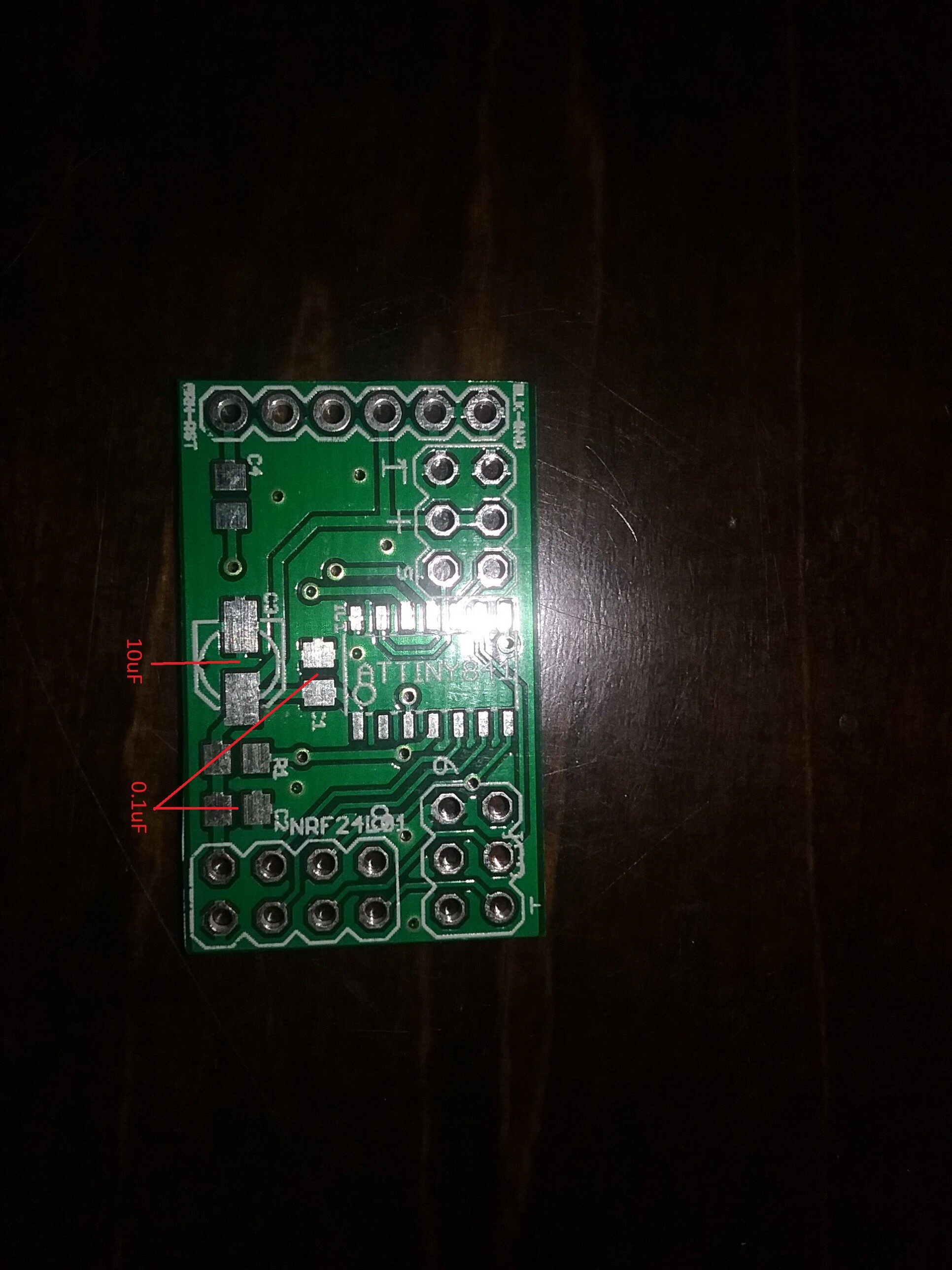
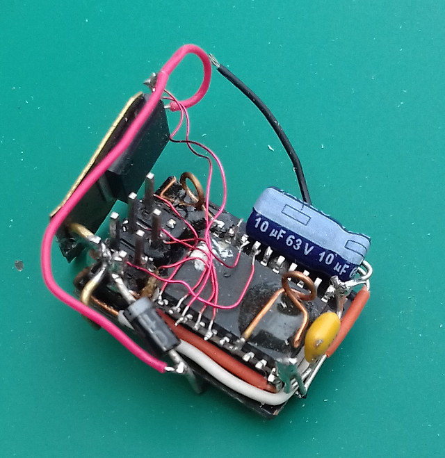
Pictures of my board are attached.
Any help would be appreciated.