I am using Nano 33 BLE Sense and tried the rgb example.
But the green LED is not working.
I have define Ports as follows:
#define RED 22
#define BLUE 24
#define GREEN 23
#define LED_PWR 25
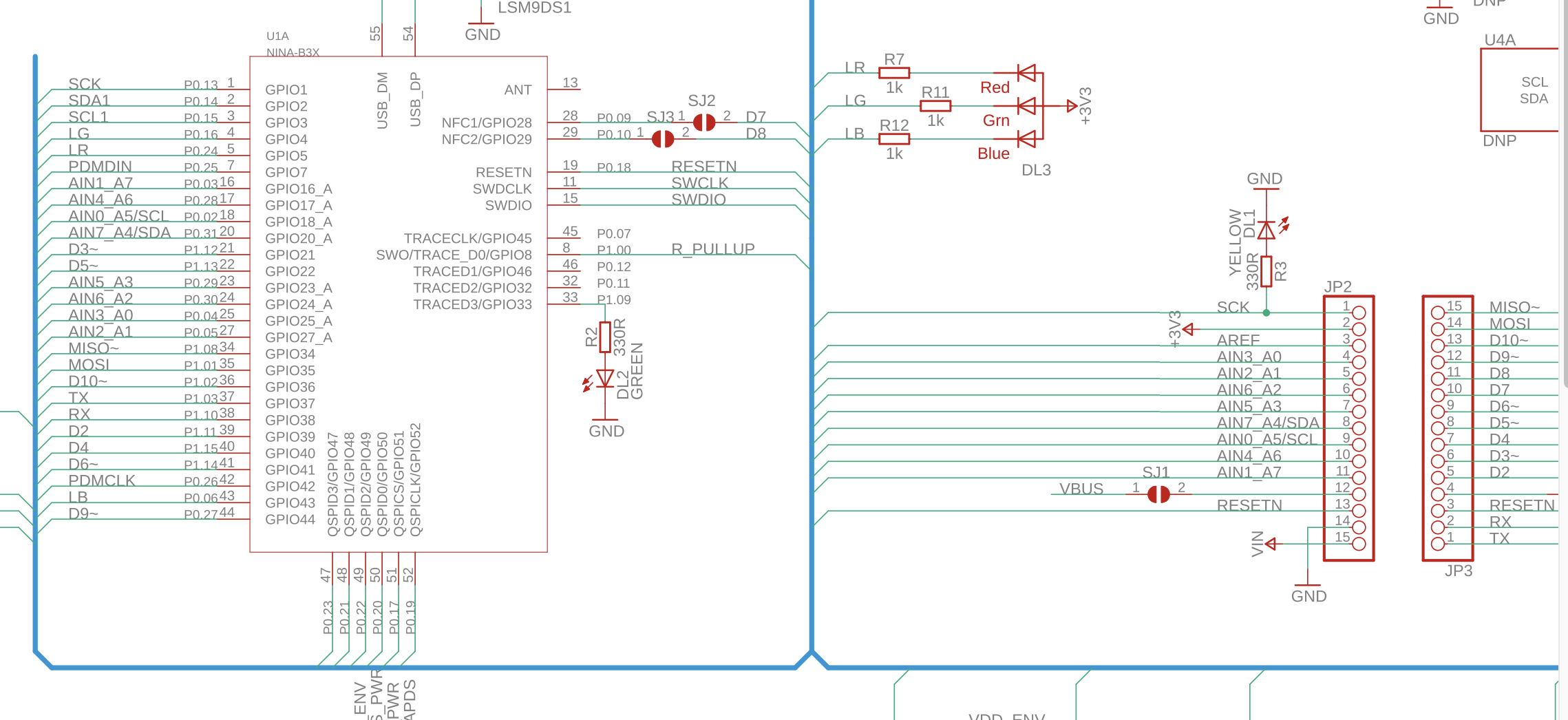
But If i look into the schematics.
https://content.arduino.cc/assets/NANO33BLE_V2.0_sch.pdf
I can see that the led are connected to this ports.
LED_BUILTIN port 13
LED GREEN 16
LED RED 24
LED BLUE 6
Why is this discrepancy.... br joachim
Does the unmodified example code you linked not work? If not, perhaps the green LED is defective.
You appear to be confusing the port bit designations with the Arduino pin IDs.
For example, in the schematic, the green LED (designation LG) is connected to bit 16 of Port 0 (P0), also called GPIO4, which is mapped to some Arduino pin number in the boards file.
// How to control the RGB Led and Power Led of the Nano 33 BLE boards.
// the green led is not working,
#define RED 24
#define BLUE 23
#define GREEN 22
#define LED_BUILTIN 13

void setup() {
  // initialize the digital Pin as an output
  pinMode(RED, OUTPUT);
  pinMode(BLUE, OUTPUT);
  pinMode(GREEN, OUTPUT);
  pinMode(LED_BUILTIN, OUTPUT);
  pinMode(LEDR, OUTPUT);
}
// the loop function runs over and over again
void loop() {
  digitalWrite(RED, 0);  // turn the LED off by making the voltage LOW
  delay(100);            // wait for a second
  digitalWrite(RED, 1);  // turn the LED off by making the voltage LOW
  delay(100);            // wait for a second

  digitalWrite(GREEN, 1);  // turn the LED off by making the voltage LOW
  delay(100);            // wait for a second

  digitalWrite(BLUE, 0);  // turn the LED off by making the voltage LOW
  delay(100);            // wait for a second
  digitalWrite(BLUE, 1);  // turn the LED off by making the voltage LOW
  delay(100);            // wait for a second

  digitalWrite(LED_BUILTIN, 1);  // turn the LED off by making the voltage LOW
  delay(100);            // wait for a second
  digitalWrite(LED_BUILTIN, 0);  // turn the LED off by making the voltage LOW
  delay(100);            // wait for a second
}
the blue and red led will not light up, if I set GREEN LED to 0.
but I can't see any correspondence to the numbers 24,23 and 22.
Those are defined by Arduino, somewhere else. The comments in the code you posted are wrong, and do not make sense. Please try the original code from the link (copied below) and state what happens with the red, green and blue LEDs when it runs.
EDIT: the comments here are wrong, too, according to the schematic. LOW should turn the LED ON.
// How to control the RGB Led and Power Led of the Nano 33 BLE boards.

 #define RED 22
 #define BLUE 24
 #define GREEN 23
 #define LED_PWR 25

void setup() {

 // initialize the digital Pin as an output
  pinMode(RED, OUTPUT);
  pinMode(BLUE, OUTPUT);
  pinMode(GREEN, OUTPUT);
  pinMode(LED_PWR, OUTPUT);

}

// the loop function runs over and over again
void loop() {
  digitalWrite(RED, LOW); // turn the LED off by making the voltage LOW
  delay(1000);            // wait for a second
  digitalWrite(GREEN, LOW);
  delay(1000);
  digitalWrite(BLUE, LOW);
  delay(1000);
  digitalWrite(RED, HIGH); // turn the LED on (HIGH is the voltage level)
  delay(1000);
  digitalWrite(GREEN, HIGH);
  delay(1000);
  digitalWrite(BLUE, HIGH);
  delay(1000);
  digitalWrite(LED_PWR, HIGH);
  delay(1000);
  digitalWrite(LED_PWR, LOW);
  delay(1000);
}
// How to control the RGB Led and Power Led of the Nano 33 BLE boards.
 #define RED 22
 #define BLUE 24
 #define GREEN 23
 #define LED_PWR 25

void setup() {
 // initialize the digital Pin as an output
  pinMode(RED, OUTPUT);
  pinMode(BLUE, OUTPUT);
  pinMode(GREEN, OUTPUT);
  pinMode(LED_PWR, OUTPUT);
}

// the loop function runs over and over again
void loop() {
  digitalWrite(RED, LOW); // turn the LED off by making the voltage LOW
  delay(1000);            // wait for a second
  digitalWrite(GREEN, LOW);
  delay(1000);
  digitalWrite(BLUE, LOW);
  delay(1000);
  digitalWrite(RED, HIGH); // turn the LED on (HIGH is the voltage level)
  delay(1000);
  digitalWrite(GREEN, HIGH);
  delay(1000);
  digitalWrite(BLUE, HIGH);
  delay(1000);
  digitalWrite(LED_PWR, HIGH);
  delay(1000);
  digitalWrite(LED_PWR, LOW);
  delay(1000);
}
but only the power led and the red led are blinking. br joachim
What do you see when you separate the colors like this
// How to control the RGB Led and Power Led of the Nano 33 BLE boards.
#define RED 22
#define BLUE 24
#define GREEN 23
#define LED_PWR 25

void setup() {
  // initialize the digital Pin as an output
  pinMode(RED, OUTPUT);
  pinMode(BLUE, OUTPUT);
  pinMode(GREEN, OUTPUT);
  pinMode(LED_PWR, OUTPUT);
}

// the loop function runs over and over again
void loop() {
  digitalWrite(RED, LOW); // turn the LED off by making the voltage LOW
  delay(1000);            // wait for a second
  digitalWrite(RED, HIGH); // turn the LED on (HIGH is the voltage level)
  delay(1000);

  digitalWrite(GREEN, LOW);
  delay(1000);
  digitalWrite(GREEN, HIGH);
  delay(1000);

  digitalWrite(BLUE, LOW);
  delay(1000);
  digitalWrite(BLUE, HIGH);
  delay(1000);

  digitalWrite(LED_PWR, HIGH);
  delay(1000);
  digitalWrite(LED_PWR, LOW);
  delay(1000);
}
If the example code from Arduino does not run as expected, you may have a defective board.
Please run this program and state what happens (I don't have that board to test). LOW should turn ON the red LED, then it should go off after one second.
// How to control the RGB Led and Power Led of the Nano 33 BLE boards.
 #define RED 22

void setup() {
 // initialize the digital Pin as an output
  pinMode(RED, OUTPUT);
  digitalWrite(RED, LOW); // turn the LED ON by making the voltage LOW
  delay(1000);
  digitalWrite(RED, HIGH); // turn the LED off by making the voltage HIGH
}
void loop() {}
// How to control the RGB Led and Power Led of the Nano 33 BLE boards.
#define RED 22
#define BLUE 24
#define GREEN 23
#define LED_PWR 25

void setup() {
  // initialize the digital Pin as an output
  pinMode(RED, OUTPUT);
  pinMode(BLUE, OUTPUT);
  pinMode(GREEN, OUTPUT);
  pinMode(LED_PWR, OUTPUT);
  Serial.begin(115200);
  digitalWrite(LED_PWR, LOW);
  digitalWrite(RED, HIGH);
  digitalWrite(GREEN, HIGH);
  digitalWrite(BLUE, HIGH);
  digitalWrite(RED, LOW);       // turn the LED ON by making the voltage LOW
  delay(1000);                  // wait for a second
  digitalWrite(GREEN, LOW);     // turn the LED ON by making the voltage LOW
  delay(1000);                  // wait for a second
  digitalWrite(BLUE, LOW);      // turn the LED ON by making the voltage LOW
  delay(1000);                  // wait for a second
  digitalWrite(LED_PWR, HIGH);  // turn the LED ON by making the voltage HIGH
  delay(1000);                  // wait for a second
}
// the loop function runs over and over again
void loop() {
}
if i run that only the power led is on at the end.
if I turn on only one led respectively, only the pwr_led will turn on
if i turn on the red led, no led will turn on
if i turn on the green led, the blue led will turn on
if i turn on the red led the blue led will turn on.
rather strange...
I think as well the board is defective.
br
// How to control the RGB Led and Power Led of the Nano 33 BLE boards.
 #define RED 22

void setup() {
 // initialize the digital Pin as an output
  pinMode(RED, OUTPUT);
  digitalWrite(RED, LOW); // turn the LED ON by making the voltage LOW
  delay(1000);
  digitalWrite(RED, HIGH); // turn the LED off by making the voltage HIGH
}
void loop() {}
Sorry, I have no idea what is going on. The schematic could be wrong (it shows a common anode RGB LED, with the anode connected to 3.3V), or the pin designations are wrong, or some parts or connections are defective.
You could try this from the "cheat sheet", which uses different names for the LED pins:
However, the HIGH/LOW versus ON/OFF disagree with the schematic. Something is very wrong with the documentation or the schematic.
RGB

To turn ON the pixels, write a

HIGH

state to the LED:

digitalWrite(LEDR, HIGH); //RED

digitalWrite(LEDG, HIGH); //GREEN

digitalWrite(LEDB, HIGH); //BLUE

To turn OFF the pixels, write a

LOW

state to the LED:

digitalWrite(LEDR, LOW); //RED

digitalWrite(LEDG, LOW); //GREEN

digitalWrite(LEDB, LOW); //BLUE

We can also choose a value between 255 - 0 to write to the LED:

analogWrite(LEDR, 72);  //GREEN

analogWrite(LEDG, 122); //BLUE

analogWrite(LEDB, 234); //RED
Hmm. I'm not finding a lot of actual info on the "BLE Sense" - the links on the product page for schematic and EAGLE files both end up linking to files for the "Nano BLE" (without the sensors.)
And I don't see a separate board type, variant (where arduino pin numbers are mapped to chip pins), or any examples for the BLE Sense. I suppose it could be exactly a Nano BLE with all of the sensors connected to the I2C bus, but there's no way to tell. Grr.
(Looking at the photos, it seems that the NanoBLE board is the same as the BLE Sense, but with the sensors not populated?)
Note that the variants files already define "LEDR", "LEDG", and "LEDB"
void setup() {
  // put your setup code here, to run once:


analogWrite(LEDR, 72);  //GREEN

analogWrite(LEDG, 122); //BLUE

analogWrite(LEDB, 234); //RED
}

void loop() {
  // put your main code here, to run repeatedly:

}
This does point to a defective board. But the documentation is atrocious.
The Arduino company has been putting out lots of "unfinished" products recently, and if you look through this forum, you will see posts by any number of unhappy people on the problems they have encountered.