I'm new to Adruino, but a long time programmer. Last time I worked at the chip level was the Z80 so that will give you some idea of my age.
So I purchased a Nano 33 to build a marine refrigerator controller. The IOT was the big attraction. I soon figured out you can't easily use Bluetooth and IOT at the same time, so I decided to try (2) Nano 33's - one for the IOT and one for the Bluetooth using I2C for the communication.
I'm at point now where everything actually works. The first Arduino collects Bluetooth data and the second Arduino reads the data using the I2C connection. for the physical wiring, I followed the handy diagram at Wiring Diagram
The program follows below. Here is the weirdness: In order to get it to work, I have to remove the A4 and A5 link. (SCL and SDA). Actually I think maybe just the SCL.
Then after the IOT is (mostly) stable, make the connection. Then it will run (indefinitely I think) and receives the I2C data from the master Nano.
I've tried various ways to get it to start with the pins connected; no luck. Things like delaying the wire start for 30 seconds, testing for IOT connection first, etc.
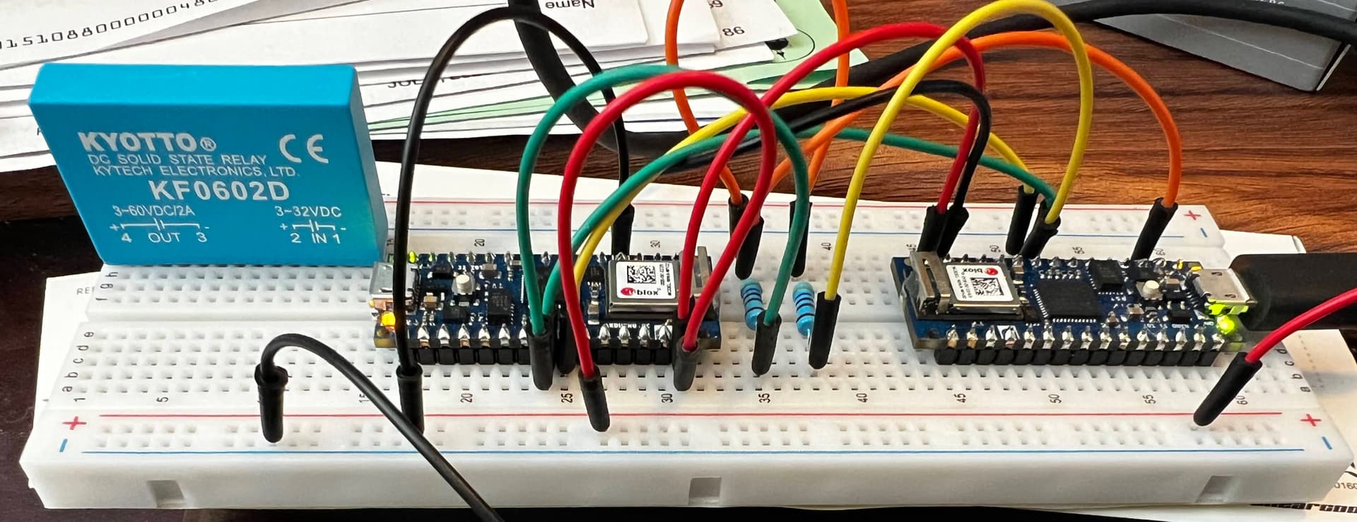
So basically the Issue seems to be that if the clock is connected when the sketch starts, it hangs, and I haven't figured a workaround. Any insights? Code and breadboard pic below:
Edit: In the breadboard pic the Bluetooth "writer" is on the left (that always works fine with I2C) and the problematic IOT "reader" on the right.
#include "arduino_secrets.h"


#include "thingProperties.h"
#include <Wire.h>

const byte flashRate = 25;
boolean wireStarted = false;
unsigned long int flashCount = 0;
short int ledState = HIGH;


void setup() {
  // Initialize serial and wait for port to open:
  Serial.begin(9600);
  pinMode(LED_BUILTIN, OUTPUT);
  digitalWrite(LED_BUILTIN, ledState);

  // This delay gives the chance to wait for a Serial Monitor without blocking if none is found
  delay(1500);

  // Defined in thingProperties.h
  initProperties();

  // Connect to Arduino IoT Cloud
  ArduinoCloud.begin(ArduinoIoTPreferredConnection);

  /*
     The following function allows you to obtain more information
     related to the state of network and IoT Cloud connection and errors
     the higher number the more granular information you’ll get.
     The default is 0 (only errors).
     Maximum is 4
 */
  setDebugMessageLevel(4);
  ArduinoCloud.printDebugInfo();

  message = "Startup Fridge State**";

  Serial.println("Starting wire...");
  wireStarted = true;
  Wire.begin(8);                 // join i2c bus with address #8
  Wire.onReceive(receiveEvent);  // function that executes whenever data is received from writer

  Serial.println("Startup done.");
}

void receiveEvent(int howMany) {
  for (int i = 1; i <= howMany; i++) {
    char c = Wire.read();  // receive a character
    Serial.println(c);
  }
}

void loop() {

  ArduinoCloud.update();


  if (flashCount++ >= flashRate) {
    // medium blink = running
    digitalWrite(LED_BUILTIN, ledState = !ledState);

    flashCount = 0;
  }
}


/*
  Since FridgeCompressorCutin is READ_WRITE variable, onFridgeCompressorCutinChange() is
  executed every time a new value is received from IoT Cloud.
*/
void onFridgeCompressorCutinChange() {
  // Add your code here to act upon FridgeCompressorCutin change
}

/*
  Since FreezerCompressorCutin is READ_WRITE variable, onFreezerCompressorCutinChange() is
  executed every time a new value is received from IoT Cloud.
*/
void onFreezerCompressorCutinChange() {
  // Add your code here to act upon FreezerCompressorCutin change
}

/*
  Since FridgeCompressorCutout is READ_WRITE variable, onFridgeCompressorCutoutChange() is
  executed every time a new value is received from IoT Cloud.
*/
void onFridgeCompressorCutoutChange() {
  // Add your code here to act upon FridgeCompressorCutout change
}