One wire DS18B20 reading +85°C, then -127°C and Arduino hanging up completely

Dear "TomeGeorge",

Yes, of course I have all the caps I need and many more protection things on it. I don't have the Nano now nearby me, but I remember there is this pin called "VCC" or "VDD" or similar and here I connect the 5V to it, as far as I remember.

Dear "gilshultz",
I repeat again: I cannot upload any things. And: I repeat again: No part is getting even warm! And it's clear to me for all the hardware, that I must meet all datasheet spec points of all the components to work properly and how to test them and how to design them, so in short, I am pretty sure that I have fulfilled them. But finally it was you, who gave me the hint about bad connection, and since I played around with the shitty connector, the 1-wire bus is working at the moment since then without any error. BIG THANKS FOR THAT!
For the software, however, I am not so sure, if I fulfill all the spec points of the datasheets.

Dear "Proietti",
I do not use any pull-down ( = to gnd !) resistor for the 1-wire bus.


Anyway, thanks guys for your inputs about the hardware, BUT: Could anyone PLEASE go through my software code? Here I would need your support. Is the code, as I have programmed it with the help of all the pre-defined libraries, according to the datasheets? Why is the uC sometimes then hanging up completely at all? I thought I will use Arduino, because I really do not want to bother with buffer overruns and pointers out of scope and similar stupid errors! These should handle the Arduino or the pre-defined libaries I have downloaded in, I hope, not version v1.0. I only want to write a code line, e.g. "sensor_bus.requestTemperatures();" and it should read the temperatures and that's it! But for the SW, the problems are starting for me: One guy says: Add "delay(1000); ", another guy says: "No!" (see e.g. "Why does this fix work for DS18B20 error code 85"). For a hardware problem I would know exactly what to do, but here in SW, I only of course tried also here just a lot of combinations to add on different places a delay here or there or add "request temps." after a "begin", as it also was proposed in the Arduino forum help, and so on, but nothing helped for me. What did help, it seems up to now, against the -127°C and +85°C error was unplug and re-plug the 3 pin 1-wire connector to all the 7 sensors. But 1st: It's illogical to me, why then just one sensor had this problem of the 85° and it could be healed with hardware, it seems, and 2nd: I think, all this has nothing to do with that the Arduino hangs up after days or e.g. also 2 weeks. I learned in the past that there is a limit on 58 days or so, but this is significantly more time than some days.
So any `wise suggestions here?

Thanks in advance,
bernd2700

Okay, you need to connect the 5V supply to the 5V pin of the Nano, there is a pin called Vin, that needs 7V - 12V.
Vin connects to an onboard 5V regulator, and feeding it with 5V will not ensure a regulated 5V supply for the Nano or peripherals.

Tom.. :smiley: :+1: :coffee: :australia:

The "85" tells you you have not given the sensor enough time to do its job, and the specific sensor is the first one sensed. Assuming a kosher power supply, a delay(1000); in setup will probably fix it - permanently. The "-127 sometimes" tells you that your peripheral connections are slack-arsed. It could be that your power connections are no better, and your problems are (nearly) all down to bad soldering. There appears to be nothing abnormal about your cable lengths, indeed quite the opposite, so you use a 4.7k pullup like the good book says.
The sensors do their internal processing independently of Arduino. You can have a swag of sensors working in a one second loop. I doubt there is any point in going any faster. Your code, as the picture below will attest, is a verbose insult but, since you do seem to get a result occasionally, there may actually be nothing much wrong with it.

Dear "Nick_Pyner",

Many thanks you for your anser! I do not understand the following fact: You say: "The "85" tells you you have not given the sensor enough time to do its job" , but on the other side: As soon as I played around with a 3 pin conncector (Hardware!), all these -127°C and also the +85° issue is GONE and, up to today (16.10.22), never appeared again. So, either I have written the software (not good enough) that the sensor does not have enough time to do its job or it has enough time, but - please agree or disagree with my opinion - this should NOT BE DEPENDENT on a good or bad HW connection?!! Only the 1-wire temp sensors and a flow meter are connected over "special" (but obviously shitty) connectors to the Arduino, the rest is connected over good connectors or soldered, and all soldered very well. But the flow meter absolutely always worked since the beginning and never ever failed. I do soldering since I am a child and did 1000s of components including a lot of SMD 0.5mm chips. There was not a single one which did not work, so we can assume, all the soldering in this project is also done decently.
And what I also do not understand: For me your post contains one contradition: You write on the one side, that the sensor does not have enough time, on the other side you write "...since you do seem to get a result occasionally, there may actually BE NOTHING MUCH WRONG..." So, is my code good or wrong now?
What I also did not understand, sorry, is the part, that my code "... is a verbose insult..." . What do you mean? I absolutely have no clue of understanding. I looked up in the dictionary again, and it returns me "affront, offend, and outrage". From where in your posted screenshot of my code, I offend someone or something, or????? Please re-state, thanks!
Anyway, since, as said, I tried a lot of combinations where to insert the delay, please tell me exactly the code line where you would insert this delay, thanks!
Finally: You write "so you use a 4.7k pullup like the good book says.". Absolutely NO, guys!! I think I have to repeat the 3rd time here: I use 1k (ONE) as a pull-up resistor on the 1-wire bus, I neither use a pull-down nor I use 4k7, ok?

If you want to do it ‘your way’ - great… many discoveries are made that way.

Just keep in mind, I2C is a ‘standard’, and there’s a lot of research and documentation that will help when following the standards.

Not quite, but you might say it has enough time now that you have played around with the three pin connector.
To reiterate more clearly, the 85 tells you the sensor has not had time to do its job. This can be either from power-on, or the last time it delivered a reading. Note that "power on" includes restoration of power after involuntary power-off,
i.e. slack-arsed soldering, or other means of bad connection.

The only reason ever for using a smaller pullup than what the manufacture recommends is when you have long sensor cables. "Long" normally means 10m, in which case a 2.2k may be a solution, but never less, and I don't think it applies here anyway. I have never heard of anybody using a 1k and I think it is fair to say that there are only two people in the known universe who do that - you, and the idiot who told you it is a good idea, and I wouldn't be too sure about him either. I don't know if a 4.7k will solve your problem but, until you do it the way God and Maxxim intended, you deserve all the grief you are getting. By all means use a 1k later, after you have gotten a proper result by using a kosher pullup. That way you might at least get to have the last laugh, but you can be sure nobody will be listening.

No. The only time you assume that is when everything works as intended, and it seems pretty clear here that all your problems have been down to bad hardware connections.

As for the code, see reply #6. Not only is there way too much, but also most of it is rubbish - hence the picture.

I have to apologize, since English is not my mother language, I think I formulated my statement in a wrong way. I did not want to “insult” anyone (if I use that word correctly). With my statement “Absolutely NO”, I only wanted to make clear: “At the moment I am using this value, not any other value.” (because you have written “so you use a 4.7k pullup” => NO, I am not yet!) But this does NOT mean for me that I am not WILLING to use another value. If everyone is using 4k7, it seems, then why not also change to 4k7? It’s just un- and resoldering 1 single resistor done in 10 min.!
However, I stick to my sentence “Soldering = assumed done well”. It is / was a problem due to purchased shitty connectors, not due to my soldering.
Last thing: About my “rubbish” code. Why??? I mean: Why is most of my code rubbish? The whole thing is operating now 24h a day since “gilshultz” was giving me a very nice hint in post #5, so since 13.1022 now without ANY error so far. I repeat, I am not so good with software, but this fact makes me believe that most of my code cannot be SO rubbish if it seems to work now! But if you say so, that “most of my code is rubbish” then you are cordially invited to correct it, please, that’s what I exactly ask all the time. But “support” for me does not mean, that just anyone says: “That’s all (sorry: “most”) rubbish”. This is no support for me. But rather, to make a precise suggestion what is not good in my code and how to correct. Please, then, at least tell me all the faulty code lines / segments, and how to replace them with a better code, and this for me, as a non-professional software guy, means: In CONCRETE what to write in C so that I can learn and understand. Just saying “that’s rubbish” is worthless for me and maybe also for all the other readers who might have had / will have in the future the same or a similar problem. And, as I said: I do not dare to leave out any code sections to post, because exactly this may then be the cause of the hang-up you professionals see but I am overlooking. This is my thinking.

==> So, therefore: Is there anyone please in this forum who is willing to check my code and maybe spot a point which could lead to a potential hang-up of the Arduino and how to correct it? (It’s working now since 13.10.22 without interruption but I am just waiting for it to happen.) THIS would help me!

Many thanks and sorry for any inconveniences caused,
bernd2700

As I believe I said in post #23, your problem probably has nothing to do with code and everything to do with bad connections. That said, you post code so that somebody else can read through it, and posting the entire code that shows the problem is prerequisite. That does not mean code that is full of junk, comments, and whitespace. In your case, a 50 -line tutorial would have given the same reult and was just as valid. What you posted was 825 lines long and so obviously full of junk it wasn't worth reading, so did you seriously expect somebody to scroll through all that on the off-chance that something might be wrong with it? I might point out that some people are on this forum with just a phone.....

The following edit is 546 lines long and, if you bother to run it, you might never know the difference! If you can get it down to 413 lines with the same result, it wouldn't surprise me. There is I2C scanner stuff, parasite power, several dozen useless serial.prints, and God only knows what other redundant or irrelevant stuff stashed away in there - all clogging up the forum code-window. As I said, a bloody insult, as the posted picture above shows....

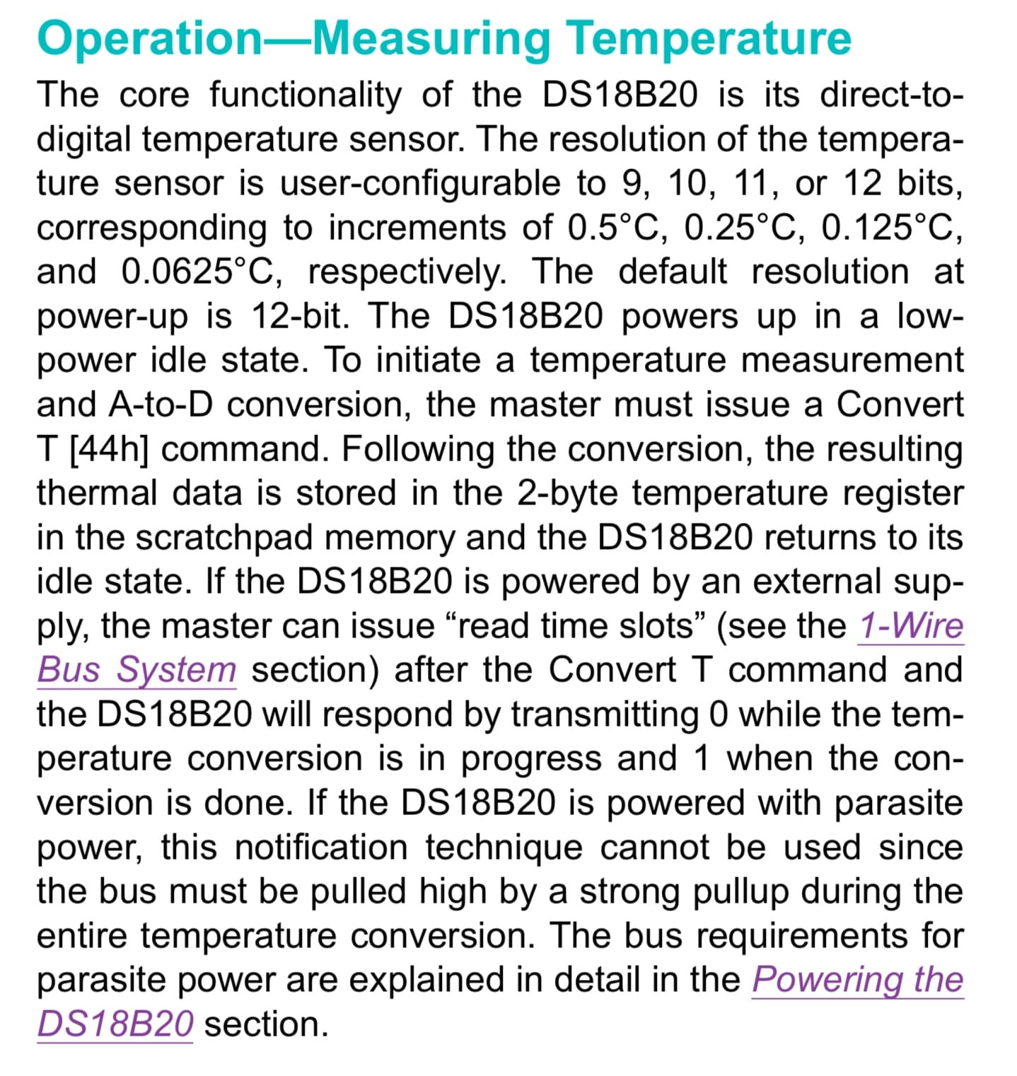
FWIW, the DS18B20 has 12bit resolution by default.

Your English is fine - better than a recent President of the United States.


  #include <Arduino.h>
  #include <U8x8lib.h>
  #include <OneWire.h>
  #include <DallasTemperature.h>
  #include "MCP3221.h"

 const float VCC_VREF_V = 5.02;    // Voltage reference ( = VCC) for in units [V]

  #define ENABLE_SEARCH_ADDRESS           // Use the ENABLE_SEARCH_ADDRESS to gather all the unique addresses of the sensors. Comment it out if you don't want to use it.
  #define ENABLE_READ_BACK_RESOLUTION     // Use the ENABLE_READ_BACK_RESOLUTION to confirm that the right resolution has been set.
  #define ONE_WIRE_BUS 2                  // Data wire is plugged into port 2 on the Arduino;  Make sure a pull-up resistor (e.g. 1k) is connected (so from Data to VCC)
  #define TEMPERATURE_PRECISION 12        // 12 is maximum but slower.
  #define NUM_OW_SENSORS 8                // the number of DS18B20 sensors on the 1-Wire bus.

    const DeviceAddress sensor_address[NUM_OW_SENSORS] =
    {
      { 0x28, 0x41, 0x6B, 0x07, 0xD6, 0x01, 0x3C, 0xAA },   // S01_ColdIntoPWT   = TempSensors_Temps[0]
      { 0x28, 0x4F, 0xEA, 0x07, 0xD6, 0x01, 0x3C, 0xBF },   // S02_ColdFromPWT   = TempSensors_Temps[1]
      { 0x28, 0xCF, 0xC2, 0x07, 0xD6, 0x01, 0x3C, 0x93 },   // S03_HotFromCompr  = TempSensors_Temps[2]
      { 0x28, 0xD4, 0x45, 0x07, 0xD6, 0x01, 0x3C, 0xAA },   // S04_HotFromPWT    = TempSensors_Temps[3]
      { 0x28, 0xC9, 0x05, 0x07, 0xD6, 0x01, 0x3C, 0x52 },   // S05_AmbientOfUnit = TempSensors_Temps[4]
      { 0x28, 0xAA, 0xD5, 0xAC, 0x1D, 0x13, 0x02, 0xE5 },   // S06_InsideFluid   = TempSensors_Temps[5]
      { 0x28, 0xD4, 0xD1, 0xEA, 0x32, 0x14, 0x01, 0xDF },   // S07_CoolBoxS01    = TempSensors_Temps[6]
      { 0x28, 0xAA, 0xC3, 0xDB, 0x1D, 0x13, 0x02, 0x2B },   // S08_CoolBoxS02    = TempSensors_Temps[7]
    };

  // Create labels in PROGMEM, see : https://www.arduino.cc/en/Reference/PROGMEM ; The order of the labels must match the order of the addresses in 'sensor_address[]'.
    const char string0[] PROGMEM = "S01_ColdIntoPWT";
    const char string1[] PROGMEM = "S02_ColdFromPWT";
    const char string2[] PROGMEM = "S03_HotFromCompr";
    const char string3[] PROGMEM = "S04_HotFromPWT";
    const char string4[] PROGMEM = "S05_AmbientOfUnit";
    const char string5[] PROGMEM = "S06_InsideFluid";
    const char string6[] PROGMEM = "S07_CoolBoxS01";
    const char string7[] PROGMEM = "S08_CoolBoxS02";
    
    const char * const string_table[] PROGMEM =
    {
      string0, string1, string2, string3, string4, string5, string6, string7,
    };
  
  const byte SLAVE1 = 0x4E;                 // I2C address of the MCP3221 for measuring the compressor current
  const byte SLAVE2 = 0x4F;                 // I2C address of the MCP3221 for measuring the pump current
  const float MPC3221_VREF_V = VCC_VREF_V;  // Voltage reference ( = VCC) for the MCP3221 in units [V]
  // Sensitivity
    const float SENS_ACS723_05__V_PER_A = 0.4;    // SENSitivity of the "ACS723LLCTR-05AB-T" in units [V/A]
    const float SENS_ACS723_10__V_PER_A = 0.2;    // SENSitivity of the "ACS723LLCTR-10AB-T" in units [V/A]    

// Internal ADC for 12V VBB (VBAT) voltage reading
  const int VBB_MEAS_ANALOG_IN_PIN = A6;          // Pin used for voltage VBB (VBAT) measurement reading through internal Arduino ADC
  const float VBB_MEAS_RES_DIV_GAIN = 4;          // Gain setting of the RESistor DIVider (potentiometer) between the VBB (VBAT) voltage (max. 20V foreseen) to VCC related (approx. 5V nom).

// Alive / Error LED
  const int AliveErrorLED = 4;                    // Pin "D4"

// Switches ( = Pushbuttons)
  #define ERROR_WINDOW_SW 50  // +/- this value
  #define DEBUG_ON
  int AnalogSwPin = 7;   // switch circuit input connected to analog pin 7

// Temperature control
  // Inside cooling box, set the initial value to which the system shall control the temperatures of the water e.g.
    float Temp_CoolBoxS02_Lo = -0.3;
    float Temp_CoolBoxS02_Hi = +0.5;
    bool Change_S01_Lo_or_Hi = false;     // If the switches / keys shall change the "Lo" or the "Hi" value of the "S01" temperature sensor.

// Compressor switch on / off
  #define ComprOnOffPin A3        // An analog hardware is connected to pin A3 which switches the relay off immediately as soon as this pin is going low. If this pin is going high, approx. 7 min has to be waited due to an RC time constant until the relay switches on. 
  bool ComprOnOff = false;        // If the compressor shall be turned on or off

  OneWire oneWire(ONE_WIRE_BUS);                          // Setup a oneWire instance to communicate with any OneWire devices (not just Maxim/Dallas temperature ICs)
  DallasTemperature sensor_bus( &oneWire);                // Pass our oneWire reference to Dallas Temperature.

// OLED-Display
  U8X8_SH1106_128X64_NONAME_HW_I2C u8x8(/* reset=*/ U8X8_PIN_NONE);       // Please update the pin numbers according to your setup. Use U8X8_PIN_NONE if the reset pin is not connected

// 1-wire
  static int          CurNrOWdevsBus;                                             // Current number of 1-wire devices on the bus
  static float        TempSensors_Temps[NUM_OW_SENSORS];                          // Array which holds the current temperatures of all 1-wire temperature sensors

// Flow-sensor
  volatile  int   flow_frequency;   // Measures flow sensor pulses
            float l_minute = 0.0;   // Calculated litres/hour
  unsigned  char  flowsensor = 3;   // Sensor Input
  unsigned  long  currentTime;
  unsigned  long  cloopTime;

// MCP3221
  //static unsigned int Compr_Cur_DigCode;    // COMPRessor digital code read through MCP3221 ( 0 .. 4095 )
  static float Compr_Cur_DigCode;    // COMPRessor digital code read through MCP3221 ( 0 .. 4095 )
  static float Compr_Cur_A;          // COMPRessor CURrent read through MCP3221 stored in this variable in units "[A]"
  static float Pump_Cur_DigCode;     // PUMP       digital code read through MCP3221 ( 0 .. 4095 )
  static float Pump_Cur_A;           // PUMP       CURrent read through MCP3221 stored in this variable in units "[A]"
  static unsigned short SysErr = 0;       // If there is an error in the system, e.g. overtemperature of the compressor etc.
  static unsigned short uCalive = 1;      // Change value every e.g. 1s and display some character on OLED display

  unsigned  char  DEBUG_PIN = 4;
  
void flow () // Interrupt function
{
   flow_frequency++;
}

void func_OW_GetDevicesOnBusAndAssignAddr()
{
  // locate devices on the bus
    Serial.print("Locating One-Wire devices...");
    sensor_bus.begin();                             // Start up the library

  #ifdef ENABLE_SEARCH_ADDRESS
    // Get the number of devices on the 1-Wire bus.
      CurNrOWdevsBus = sensor_bus.getDeviceCount();
      Serial.print(F( "Number of devices found: "));
      Serial.println( CurNrOWdevsBus );
  
    // Get the unique address: Use the actual number of found sensors, to make it possible to connect the sensors one by one (and press reset every time) and see the unique address. Once all the addresses are set in 'sensor_address[]', then the index of that is used, and not the index of the DallasTemperature.
      Serial.println(F( "Copy the 8 bytes of the sensor address into the sketch."));
      DeviceAddress sens;               // temporary sensor address.
      for( int i=0; i<CurNrOWdevsBus; i++)           // this is the index for the DallasTemperature library
      {
        sensor_bus.getAddress( sens, i);
       
        Serial.print(F( "Device found, address: "));
        for( int j=0; j<8; j++)
        {
          Serial.print(F( "0x"));
          if( sens[j] < 16)
            Serial.print(F( "0"));
          Serial.print( sens[j], HEX);
          if( j!=7)
            Serial.print(F( ", "));
        }
        Serial.println();
      }
  #endif
}
void func_OW_GetTempsensorTemps()
{
  sensor_bus.requestTemperatures();   // Global request to get the temperatures  // Gather all the temperatures  // The temperatures are requested by using the unique address of the sensor. The connected sensors with its address in this sketch will return a valid temperature, regardless of other sensors that might be missing or extra sensors that might have been added.
  for( int i=0; i<NUM_OW_SENSORS; i++)
  {
    TempSensors_Temps[i] = sensor_bus.getTempC( sensor_address[i]);   // Get temperature with its own unique address.  // This matches the labels to the specific sensor.
  }

  // Print all the temperatures
    for( int i=0; i<NUM_OW_SENSORS; i++)
    {
      char buffer[40];
      strcpy_P( buffer, (char *) pgm_read_word( &(string_table[i])));
      Serial.print( buffer);
      Serial.print(F( ": "));
      if( TempSensors_Temps[i] == -127.0)
      {
        Serial.print(F( "Error, not found  "));
      }
      else
      {
        Serial.print( TempSensors_Temps[i]);
        Serial.print(F( "  "));
      }
    }
    Serial.println();
}

void func_I2C_Scanner()
{
  byte error, address;
  int nDevices;

  Serial.print(F("\n----------------------\n"));
  Serial.println("Scanning for I2C devices ...");
 
  nDevices = 0;
  for(address = 1; address < 127; address++ )
  {

    Wire.beginTransmission(address);
    error = Wire.endTransmission();
 
    if (error == 0)
    {
      Serial.print("I2C device found at address 0x");
      if (address<16)
        Serial.print("0");
      Serial.print(address,HEX);
      Serial.println("  !");
 
      nDevices++;
    }
    else if (error==4)
    {
      Serial.print("Unknown error at address 0x");
      if (address<16)
        Serial.print("0");
      Serial.println(address,HEX);
    }   
  }
  if (nDevices == 0)
    Serial.println("No I2C devices found\n");
  else
    Serial.println("done\n");
}

int buttonPushed(int pinNum) {
  int val;         // variable to store the read value
    val = analogRead(pinNum);   // read the input pin
    
    #ifdef DEBUG_ON
      Serial.println(val);
    #endif

    if ( val >= (1023-ERROR_WINDOW_SW) and val <= (1023) ) { // 1022 .. 1023
      #ifdef DEBUG_ON
      Serial.println("switch 1 pressed/triggered");
      #endif
      return 1;
    }
    else if ( val >= (681-ERROR_WINDOW_SW) and val <= (681+ERROR_WINDOW_SW) ) { // 681
      #ifdef DEBUG_ON
      Serial.println("switch 2 pressed/triggered");
      #endif
      return 2;
    }
    else if ( val >= (340-ERROR_WINDOW_SW) and val <= (340+ERROR_WINDOW_SW) ) { // 340
      #ifdef DEBUG_ON
      Serial.println("switch 3 pressed/triggered");
      #endif
      return 3;
    }
    else
      return 0;  // no button found to have been pushed
}

void setup()
{
// System LED  
  pinMode( LED_BUILTIN , OUTPUT );  

// AliveErrorLED
  pinMode( AliveErrorLED , OUTPUT );

// Compressor switch on / off
  pinMode( ComprOnOffPin , OUTPUT );

// Switches
  pinMode( AnalogSwPin , INPUT );
    
// start serial port
  Serial.begin(9600);
  while(!Serial);     // Acc. to Arduino Forum, basically: Wait for serial port to connect, necessary for some boards.  // In more detail: "On boards with an FT232 chip or other USB->Serial bridge chip (Uno, Mega, etc) it does absolutely nothing. On boards with a direct USB connection, such as the Leonardo or the Yùn it waits for an active serial connection to be established by the PC (i.e., for the serial port to be opened by a piece of software)."
  Serial.print(F("INITIATING SERIAL COMMUNICATION\n"));  
  Serial.print(F("Serial Port "));
  Serial.print(Serial ? "is open\n" : "Could not be opened\n"); 
  Serial.print(F("----------------------\n"));
    
// 1-wire
  // Get 1-wire device addresses and assign increasing integer number to them
    func_OW_GetDevicesOnBusAndAssignAddr();
    
  // Set the resolution of the 1-wire temperature sensors
    func_OW_SetGetTempDevicesProperties();

  // Get current temperatures of all 1-wire temperature sensors and store them into an array
    func_OW_GetTempsensorTemps();
    
// Flow-sensor
   pinMode(flowsensor, INPUT);
   digitalWrite(flowsensor, HIGH); // Optional Internal Pull-Up
   attachInterrupt(digitalPinToInterrupt(flowsensor), flow, RISING); // Setup Interrupt
   currentTime = millis();
   cloopTime = currentTime;

// Start communication with I2C: Needed for MCP3221
    Wire.begin();   

    func_I2C_Scanner();
    
  // MCP3221: Hint from "https://forum.arduino.cc/index.php?topic=550117.0": Summary: It works, if we move the constructors ( = "MCP3221 mcp3221A(SLAVE1);" ; "MCP3221 mcp3221B(SLAVE2);") __INTO_ "loop()", thereby constructing 2 new slave devices at each cycle like so:
    MCP3221 mcp3221A(SLAVE1);
    // Ping
      Serial.print(F("Slave A reading:\t"));
      Serial.print(mcp3221A.ping() ? (F("Not Found\n")) : (F("Found!\n")));
    // Set different things
      mcp3221A.setSmoothing(NO_SMOOTHING);
    // Get raw data
      Compr_Cur_DigCode = mcp3221A.getData();
      Serial.print(F("Compressor current still in digital code (0..4095):  "));
      Serial.print(Compr_Cur_DigCode);
      Serial.print(F("[]\n"));

    MCP3221 mcp3221B(SLAVE2);
    // Ping
      Serial.print(F("Slave B reading:\t"));
      Serial.print(mcp3221B.ping() ? (F("Not Found\n")) : (F("Found!\n")));
    // Set different things
      mcp3221B.setSmoothing(NO_SMOOTHING);
    // Get raw data
      Pump_Cur_DigCode = mcp3221B.getData();
      Serial.print(F("Pump current still in digital code (0..4095):  "));
      Serial.print(Pump_Cur_DigCode);
      Serial.print(F("[]\n"));
      
    u8x8.begin();
    u8x8.setPowerSave(0);
  
  // Write OW devices with addresses to OLED-Display
    u8x8.setFont(u8x8_font_chroma48medium8_r);
    u8x8.drawString(0,0,"Nr Devs OW bus:");
    u8x8.setCursor(0,1);
    u8x8.print(CurNrOWdevsBus);
    //u8x8.drawString(0,1,CurNrOWdevsBus_char);
    u8x8.refreshDisplay();    // only required for SSD1606/7  

  delay(2000);
  u8x8.clear();
}

void loop()
{
  currentTime = millis();
  
// Every second, calculate and print litres/hour
  if(currentTime >= (cloopTime + 2000))
  {
   if(flow_frequency != 0){
        l_minute = 1000.0 / (currentTime - cloopTime) * (flow_frequency / 7.5); // (Pulse frequency x 60 min) / 7.5Q = flowrate in L/hour   // "1000.0 / (currentTime - cloopTime)" = Correction if loop takes longer than "1000" ms.
        flow_frequency = 0; // Reset Counter
        l_minute = l_minute * 0.9;  // Correction: 3.0 l/min from Wasseruhr, YF-S201 displayed 3.33 l/min.  => After this correction measured approx. correct at least with flow rates checked with 1 (one) l/min, and 3 l/min (on 21.02.2021).
  // Durchfluss-Sensor brauch erneute Kalibration nachdem die LoopTime ohne Delay umgestellt worden ist!!
      }
      else {
        l_minute = 0;   // To not keep the last value forever if there is no more flow.
      }
  
    // Reset the time count right after (in order that not even more time passes than 1000ms) the Flow-Sensor but also not before it (otherwise calibration of flow sensor will fail, see there).
      cloopTime = currentTime; // Updates cloopTime
 
        func_OW_GetTempsensorTemps();

      // Still just for fun:
        int countAbove70 = 0;
          for( int i=0; i<NUM_OW_SENSORS; i++)
          {
            if( TempSensors_Temps[i] > 86.0)
            {
              countAbove70++;
            }
          }
          Serial.print(F( "There are "));
          Serial.print( countAbove70);
          Serial.println(F( " sensors above 70.0"));
          if( countAbove70 > 0)           // at least one sensor above 70 degrees ?
          {
            SysErr = 1;
          }
          else
          {
            SysErr = 0;
          }

        MCP3221 mcp3221A(SLAVE1);
        mcp3221A.setSmoothing(NO_SMOOTHING);      // Obviously has to be repeated here in the loop. Is not enough to once define it in the setup.
        Compr_Cur_DigCode = mcp3221A.getData();
        MCP3221 mcp3221B(SLAVE2);
        mcp3221B.setSmoothing(NO_SMOOTHING);      // Obviously has to be repeated here in the loop. Is not enough to once define it in the setup.
        Pump_Cur_DigCode = mcp3221B.getData();
        Serial.print(F("Compressor current still in digital code (0..4095):  "));
        Serial.print(Compr_Cur_DigCode);
        Serial.print(F("[]\n"));
        Serial.print(F("Pump current still in digital code (0..4095):  "));
        Serial.print(Pump_Cur_DigCode);
        Serial.print(F("[]\n"));
      // Convert raw data to current
        Compr_Cur_A = MPC3221_VREF_V * ( 2 * Compr_Cur_DigCode - 4096 ) / ( 4096 * 2 * SENS_ACS723_10__V_PER_A );
        Pump_Cur_A  = MPC3221_VREF_V * ( 2 * Pump_Cur_DigCode  - 4096 ) / ( 4096 * 2 * SENS_ACS723_05__V_PER_A );
      // Print converted currents to Amperes to serial
        Serial.print(F("Compressor current in units [A]:  "));
        Serial.print(Compr_Cur_A);
        Serial.print(F("[]\n"));
        Serial.print(F("Pump current in units [A]:  "));
        Serial.print(Pump_Cur_A);
        Serial.print(F("[]\n"));
                    VBBmeas_ADC_val_DigCode = analogRead( VBB_MEAS_ANALOG_IN_PIN );
      VBBmeas_ADC_val_V = VBBmeas_ADC_val_DigCode * ( VCC_VREF_V / 1024 );
      VBBmeas_VBB_V = VBBmeas_ADC_val_V * VBB_MEAS_RES_DIV_GAIN;

    // Switches
        int buttNum = buttonPushed(AnalogSwPin);
        
        #ifdef DEBUG_ON
          Serial.print("Button "); Serial.print(buttNum); Serial.println(" was pushed.");  
        #endif
        
        if ( Change_S01_Lo_or_Hi == false ) {           // If "Change_S01_Lo_or_Hi" = e.g. Lo ( = e.g. "false") ==> Allow to modify the "Lo" value with the switches / keys.
          if ( buttNum == 1 ) {
            Temp_CoolBoxS02_Lo = Temp_CoolBoxS02_Lo + 0.1;
          }
          else if ( buttNum == 2 ) {
            Temp_CoolBoxS02_Lo = Temp_CoolBoxS02_Lo - 0.1;
          }   
        }
        else {                                          // If "Change_S01_Lo_or_Hi" = e.g. Hi ( = e.g. "true") ==> Allow to modify the "Hi" value with the switches / keys.
          if ( buttNum == 1 ) {
            Temp_CoolBoxS02_Hi = Temp_CoolBoxS02_Hi + 0.1;
          }
          else if ( buttNum == 2 ) {
            Temp_CoolBoxS02_Hi = Temp_CoolBoxS02_Hi - 0.1;
          }
        }

        if ( buttNum == 3 ) {                           // Button nr. 3 changes the modification of either the "Lo" or "Hi" value of the "S01".
          Change_S01_Lo_or_Hi = !Change_S01_Lo_or_Hi;
        }

      // Higher limit must be higher than the lower limit, because it does only cooling
        if ( Temp_CoolBoxS02_Lo >= Temp_CoolBoxS02_Hi ) {
          Temp_CoolBoxS02_Hi = Temp_CoolBoxS02_Lo + 1;
        }
        
        #ifdef DEBUG_ON
          Serial.print("Temp_CoolBoxS02_Lo = "); Serial.println(Temp_CoolBoxS02_Lo);
          Serial.print("Temp_CoolBoxS02_Hi = "); Serial.println(Temp_CoolBoxS02_Hi);
        #endif

    // Compressor switch on / off control
      if ( SysErr == 1 ) {                                    // If a system error ( = e.g. critical temperature is reached anywhere) occurred ...
        ComprOnOff = false;                                   // ... turn off the compressor
      }
      else {
        if ( TempSensors_Temps[7] < Temp_CoolBoxS02_Lo ) {    // If the temperature of sensor "S02" is <= as the minimum set temperature ...
          ComprOnOff = false;                                 // ... turn off the compressor
        }
        if ( TempSensors_Temps[7] > Temp_CoolBoxS02_Hi ) {    // If the temperature of sensor "S02" is <= as the minimum set temperature ...
          ComprOnOff = true;                                  // ... turn on the compressor
        } 
      }

      if ( ComprOnOff == false ) {
        digitalWrite( ComprOnOffPin , LOW );
      }
      if ( ComprOnOff == true ) {
        digitalWrite( ComprOnOffPin , HIGH );
      }
      
        u8x8.drawString(0, 0, "CI");   // Cold Into the plate heat exchanger
        u8x8.drawString(0, 1, "CO");   // Cold Out of the plate heat exchanger
        u8x8.drawString(0, 2, "HC");   // Hot out of the Compressor
        u8x8.drawString(0, 3, "HO");   // Hot Out of the plate heat exchanger
        u8x8.drawString(0, 4, "AT");   // Ambient Temperature
        u8x8.drawString(0, 5, "IF");   // Inside Fluid
        u8x8.drawString(0, 6, "S1");   // CoolBox inside Sensor 01
        u8x8.drawString(0, 7, "S2");   // CoolBox inside Sensor 01
        for (uint8_t i = 0; i < CurNrOWdevsBus; i++) {      // If "NrOWdevs = 10", runs from 0 .. 9
          u8x8.setCursor(3,i);  // Set cursor to column 3 of display (starting with column "0")
          u8x8.print(TempSensors_Temps[i],2);
        }

            u8x8.drawString(7, 6, " ");
            u8x8.drawString(7, 7, " ");
        u8x8.drawString(9, 1, "     ");  // Obviously additionally needed to clear this part of the display, otherwise could happen, that if number falls below 4 digits (e.g. "1000"), then the last "0" remains, so e.g. if first was "1234mV" displayed, then only "980mV" that the display showed "9804mV".
        u8x8.setCursor(9,1);
        u8x8.print(l_minute,2);
        u8x8.drawString(9, 0, "CAL!");  // Durchfluss-Sensor brauch erneute Kalibration nachdem die LoopTime ohne Delay umgestellt worden ist!!
        u8x8.drawString(14, 1, "FR");
        u8x8.drawString(9, 2, "     ");  // Obviously additionally needed to clear this part of the display, otherwise could happen, that if number falls below 4 digits (e.g. "1000"), then the last "0" remains, so e.g. if first was "1234mV" displayed, then only "980mV" that the display showed "9804mV".
        u8x8.setCursor(9,2);
        u8x8.print(Compr_Cur_A , 1);     // Although "unsigned int", "1" decimal place necessary; with "0", it doesn't display the voltage
        u8x8.drawString(14, 2, "CC");   // CC = Compressor Current
        u8x8.drawString(9, 3, "     ");  // Obviously additionally needed to clear this part of the display, otherwise could happen, that if number falls below 4 digits (e.g. "1000"), then the last "0" remains, so e.g. if first was "1234mV" displayed, then only "980mV" that the display showed "9804mV".
        u8x8.setCursor(9,3);
        u8x8.print(Pump_Cur_A , 1);      // Although "unsigned int", "1" decimal place necessary; with "0", it doesn't display the voltage
        u8x8.drawString(14, 3, "PC");   // PC = Pump Current

        u8x8.drawString(9, 4, "     ");  // Obviously additionally needed to clear this part of the display, otherwise could happen, that if number falls below 4 digits (e.g. "1000"), then the last "0" remains, so e.g. if first was "1234mV" displayed, then only "980mV" that the display showed "9804mV".
        u8x8.setCursor(9,4);
        u8x8.print(VBBmeas_VBB_V , 1);     // Although "unsigned int", "1" decimal place necessary; with "0", it doesn't display the voltage
        u8x8.drawString(14, 4, "VB");   // VB = VBB (VBAT) = nom. 12V
  
        if ( ComprOnOff == false ) {
          u8x8.drawString(13, 5, "OFF");
        }
        if ( ComprOnOff == true ) {
          u8x8.drawString(13, 5, " ON");
        }

          u8x8.drawString(8, 7, "    ");
          if ( Temp_CoolBoxS02_Lo < 0 ) {
            u8x8.drawString(8, 7, "-");
          }
          else {
            u8x8.drawString(8, 7, "+");
          }
          u8x8.setCursor(9,7);
          u8x8.print( abs(Temp_CoolBoxS02_Lo) , 1);     // Although "unsigned int", "1" decimal place necessary; with "0", it doesn't display the voltage

          u8x8.drawString(12, 7, "   ");      // One blank " " less thank above ( = with "Temp_CoolBoxS02_Lo") because end column of display. 
          if ( Temp_CoolBoxS02_Hi < 0 ) {
            u8x8.drawString(12, 7, "-");
          }
          else {
            u8x8.drawString(12, 7, "+");
          }
          u8x8.setCursor(13,7);
          u8x8.print( abs(Temp_CoolBoxS02_Hi) , 1);     // Although "unsigned int", "1" decimal place necessary; with "0", it doesn't display the voltage

        switch (uCalive) {
          case 1:
            u8x8.drawString(15, 0, "-");
            uCalive = 2;
            digitalWrite( LED_BUILTIN , HIGH ); 
            digitalWrite( AliveErrorLED , HIGH );
            break;
          case 2:
            u8x8.drawString(15, 0, "\\");
            uCalive = 3;
            digitalWrite( LED_BUILTIN , LOW ); 
            digitalWrite( AliveErrorLED , LOW );
            break;
          case 3:
            u8x8.drawString(15, 0, "|");
            uCalive = 4;
            if ( SysErr >= 1 )
              digitalWrite( AliveErrorLED , HIGH );
            break;
          case 4:
            u8x8.drawString(15, 0, "/");
            uCalive = 1;
            break;
          default:
            u8x8.drawString(15, 0, "E");    // Error !
            break; // Wird nicht benötigt, wenn Statement(s) vorhanden sind
        }
}

1k need more 'power' to make the communication 0V. Maxim

Wiring the devices like say here. The star topologie isn't the most good one.

pseudo code

// DS18B20 temperaturesensor
OneWire oneWire(ONE_WIRE_BUS);
DallasTemperature sensors(&oneWire);
DeviceAddress address;
float fltTemperature;

uint32_t startTime;

float getTemperature(DeviceAddress addr) {
  return = sensors.getTempC(addr);
}


void setup() {
  sensors.setResolution(adress, 11);// resolution 11
  startTime = millis();
  sensors.requestTemperatures();
}

void loop() {
  if ( millis() > startTime + 1500) { // 1,5 second waiting after request temperature
    // for an array with addresses you can use a for loop to populate the sensors.
    // they have all enough time to convert the temperature
    fltTemperature =  getTemperature(adress);
    sensors.requestTemperatures();
    startTime = millis();
  }
}

It is better not reading the temperature every 1,5 seconde. In your case, a cool-box, don't have great value changes in a short time. 10 seconds are more.

General:

Yesterday it happened, the whole Arduino hang up. So, as I am not so good in coding, is there someone in this forum willing to skim through and check my code what I maybe did wrong, that my program hangs up?

Yesterday, I changed my pull-up from 1k to 4k7, not much of a change. One sensor then again read “+85°C” and I un- and re-plugged the power several times until it wrote a valid temperature. So for me should be (also) a software problem. But where???

Below, 2 screenshots with 4k7 as pull-up, one short, and then a zoom inside of a long pattern:


Pullup4k7_LongPattern_Scope_AnyPartZoomedIn

Dear “Nick_Pyner”

Yes, I “expect” or much better said, I would be grateful, if someone could look through my entire code and spot the problem. If I get from someone a device, they say: Its not working, And I start to unscrew (which can be challenging) it and check one after other things until I may find the problem and repair it. They do not give me the already disassembled PCB and tell me “here in this region there should be the error”. No! They "throw" me the complete thing. So, if there are some software professionals in this forum, I think they will recognize in a second my commented-out parts of code and will consume much less time, I guess, to just mentally skip reading that commented-out part in contrast to me unscrewing some devices for other people and only then start with the search for the error.

SO PLEASE, GUYS, next days I will drive away for several days, and it WOULD BE VERY BAD, IF THE ARDUINO WOULD HANG UP DURING COMPRESSOR ON of the cooling, so the compressor would run continuously 24h a day, AND EVERYTHING WOULD FREEZE and I could throw away my things there. WHERE COULD BE THE BAD PORTION IN MY CODE WHICH CAUSES THE HANG-UP OF THE ARDUINO? As I already said, with parts of my code it seemed to work, or, better said, at least I didn't recognize a hang up. Maybe just with this "full" code.

Dear “buckfast_beekeeper”

Ok, 1k needs more power than 4k7. => And what I shall do with that info?

“Wiring the devices like say ‘here’ ” => Yes, I think I did. I described my setup in post #16. And I think, it’s ok. Or what you want to tell me with your words?

About your pseudo code : Yes I think, I did similar, didn’t I?

Thanks,

bernd2700

Hi,

Why can't you, when you can post scope traces?
The above two requests will help to make our suggestions more accurate and significant.

Is this a school/college/university project?

Thanks... Tom... :smiley: :+1: :coffee: :coffee: :australia:

Nope.
Your code.

You do the requestTemperatures() and you read the temperatures without time delay. You must gives the sensors the time to compute the temperature. In my code the temperatures frow the request 1.5s before where read.

The DS18B20 has more problems to pull down with 1k then with 4k7. That Maxim in the datasheet and application notes gives 4k7 has a reason. Who knows the sensors better then Maxim? Have you made the same scope image with 1k?

In your code stay

If you use parasite power, most of the time the databus must be high.

Hi, @bernd2700

Can you please post your current code?

Does the Arduino lockup when the compressor is OFF?

Thanks.. Tom.. :smiley: :+1: :coffee: :australia:

1 Like

No, but does seem very much like a power problem.

I don't think that's quite right. I understand the sensor starts its new conversion either:
a. immediately power is applied (first request) or
b. immediately after it has delivered on the previous request (all other requests!).

in the latter case, it doesn't matter where the delay is in the loop, just so long as there is one. I believe most tutorials have the delay at the beginning of the loop, but the only real reason for this is to ensure that there is sufficient time between power-on and the first request, thereby avoiding the -85 response. In a real project, this issue is commonly taken care of by taking up time in the setup, so people then have the delay command at the end of the loop.

As a case in point, the essentials of the loop in the Hacktronics DS18B20 tutorial looks like this.

void loop(void)
{
  delay(2000); 
  sensors.requestTemperatures();
  printTemperature(insideThermometer);
  printTemperature(outsideThermometer); 
  printTemperature(dogHouseThermometer); 
} 

Since OP appears to have a GetTempsensor srtn, I believe the essentials in his loop are about the same as the above and thus the entire loop could probably be replaced by the above half-dozen lines more or less verbatim, but his code is so full of convoluted crap no-one will ever know. That doesn't mean the code doesn't work, and I suspect it does - a triumph of the Arduino IDE. One thing is pretty certain: no amount of fartarsing about with plugs will fix a code problem.

Dear „TomGeorge“,
The system somehow gave me more rights now, which obviously means, I can post images now. And of course it does not matter which image it is.!
It’s just a private project.
A foto of the hardware does not make much sense since everything is covered in a metal box and you won’t see much.
Below, please find the circuit diagram. To not get complaints about “much too much unnecessary stuff” also for the hardware schematics, I just have drawn extra for this forum in even a nice Visio drawing the following circuit diagram. But for the hardware, it’s easy for me to know and draw only the significant things into it which maybe are in conjunction with the one-wire failures I reported. But as said, for the software / code, I am not so good to decide myself which things to leave out from my complete code and which not. Therefore I decided to post the full code with everything, and I thought, for you professionals, it shouldn’t be an issue to distinguish between the relevant code lines and the others. However, to post the complete code, obviously was, also as a newbie, really a serious mistake from my side, as I got and still continued to get from some forum answers (“so full of convoluted crap”). That I do not repeat my mistake with the hardware schematic, I did, as said, only for you an own circuit diagram, with which, I hope, you are satisfied.

Dear „buckfast_beekeeper“,
Aaahh, yes, ok, great, many thanks for pointing this out! Thanks, there seems to be someone looking into my code and spotting this error (??) and, at least, writing a clear example how to do better!
So, I think I now have understood you: So I should do first a “sensor_bus.requestTemperatures();” in the setup, then I go to the main loop and first wait e.g. 2 seconds in my case until I do the for-loop to get out the temperatures “TempSensors_Temps[i] = sensor_bus.getTempC( sensor_address[i]);” and then right in the next line, I do again a “sensor_bus.requestTemperatures();”, and then I loop around the millis, so this means it waits again 2 sec., so summing up, I changed my code now to:

void func_OW_GetTempsensorTemps()
{
for( int i=0; i<NUM_OW_SENSORS; i++)
{
TempSensors_Temps[i] = sensor_bus.getTempC( sensor_address[i]);
}

void setup()
{
delay(2000); // Power up delay
Serial.begin(9600);
func_OW_GetDevicesOnBusAndAssignAddr(); // Get 1-wire device addresses and assign increasing integer number to them
func_OW_SetGetTempDevicesProperties(); // Set the resolution of the 1-wire temperature sensors
delay(2000);
sensor_bus.requestTemperatures();
delay(2000); // Especially for the flow sensor not start yet “millis” but just put a delay
func_OW_GetTempsensorTemps();
currentTime = millis();
cloopTime = currentTime;
}

void loop()
{
currentTime = millis();
if(currentTime >= (cloopTime + 2000))
{
cloopTime = currentTime;
func_OW_GetTempsensorTemps();
sensor_bus.requestTemperatures();
}
}

You see, I also added some 2sec. delays.
I cannot report yet, if it’s correcting the issue also in reality, since now it’s working with these changes, but before it was also working some time correctly before it hang up.
I have the feeling, that what you describe should act on the +85°C issue, but maybe does not act on why the uC hangs up completely from time to time. Or am I wrong? If not, where could be for this issue my hidden problem?
However, for me, 2 sec. loop time is ok, because if I would do more, e.g. 10 sec, it would need 10 sec until the press of a button is starting to become an effect.
I don*t use parasite power.

Dear „TomGeorge“ (again),
I do not dare to post my current code because then I get lots of complaints again. But in words, it is exactly the same as in my beginning apart from this change just from above from „buckfast_beekeeper“’s suggestion.
The problem is, I of course do not know when the Arduino will hang up. If it hangs up during the output pin “A3” is in high state (5V), then the compressor is turned on forever, if in low state (0V), then the compressor is off forever. But with the later case, I do not have so much of a problem for the moment being, since after one day a person can plug the whole thing off and on again, but if it hangs up in on-state, already after latest 3 hours, everything is frozen, not talking about even 24 hours continuously compressor running!

Dear “Nick_Pyner”,
Ok, and which power problem you think of in particular? I do not ramp the VCC slowly, but I just plug-in the mains 230V cable and power up should be fast. It would be nice, if you not just write “that’s a problem” but it would help me a lot more if you also add, which problem you think of it could be, in more concrete? Now, only with this info, I do not have ANY clue what to change or to measure!
Sorry, I do not understand the following: “b. immediately after it has delivered on the previous request (all other requests!).” What do the words in parenthesis mean? I can read it 100x. but I don’t understand. Please could you repeat in other words? Why it does not matter where the delay is, as long there is one? Actually, what I think now and I am getting more confused, is: Why there must be a delay at all? I mean, if the “sensor_bus.requestTemperatures();” would even need 15 sec, it will take this 15 sec to execute and ONLY THEN = when it is finished completely, it will go to the next code line and execute this, which is “func_OW_GetTempsensorTemps();”. So from another point of view: If „buckfast_beekeeper“ would be right, then my previous code, before this correction, never would have worked, would it? And also the example you gave from the “hacktronics” homepage would not work? You see guys, I am pretty confused now, maybe it’s too late to think...
What is “OP” and “srtn” in your sentence: “Since OP appears to have a GetTempsensor srtn” ?
What is “fartarsing”? I even did not find it in the dictionaries.
Finally, if you continue to write e.g. “but his code is so full of convoluted crap”, this does not help me, and, I think, also not others. I tried my best, and apart from unnecessary 27 commented-out code lines (from line 209 to 236) out of total 854, that’s 3%, the rest of my comments was important to stay in for me, and I thought maybe also for others.

Ciao,
bernd2700

Well, there you go... What a relief it is to see that. I don't suppose there is any point in asking why there is incomprehensible crap about parasite power in your code then?

Dear “Nick_Pyner”,
Ok, and which power problem you think of in particular?

An intermittent one.

One sensor then again read “+85°C” and I un- and re-plugged the power several times until it wrote a valid temperature.

Indeed one quite possibly caused by human interference. The procedure you describe above is known as fartarsing, a term only found in specialised technical dictionaries, but you should make a note of it for future reference. You are bound to need it, so write it on the wall in large letters.

Sorry, I do not understand the following: “b. immediately after it has delivered on the previous request (all other requests!).” What do the words in parenthesis mean?

Given half a chance, and reliable power, the DS18B20 operates independently of Arduino. It
1. starts reading as soon as power is supplied
2. takes a finite time to prepare its data. In your case 750ms
3. delivers said data when requested to do so by Arduino provided it has been given suffient time to prepare. IF NOT, it says 85, which is plain english for "piss off! I'm not ready"
4. takes the next reading.

There are others who can explain this better than me. What this means is that the first reading can actually be available in Setup even if it is not requested until the loop starts. Note also that the "delay" in the loop happens after "do work" irrespective of whether it is the first line of the loop or the last line

If you know what you are doing, you will never see the 85. If you don't know what you are doing, you will see the 85 once, when you switch on. No damage done.
If you see it frequently, it means you don't know what you are doing AND are abusing the system too. The only way I can think of to do this is by fartarsing with the 3pin connector so that the power to Arduino is kosher but power to sensor is not. No doubt there are other means of abuse, equally exquisite.

OP is original poster - i.e. you. SRTN is subroutine, an old term, I'm afraid, that goes back to FORTRAN or earlier, but still used. I seem to recall that you use it.

If „buckfast_beekeeper“ would be right, then my previous code, before this correction, never would have worked, would it? ....And also the example you gave from the “hacktronics” homepage would not work?

God only knows and, as I said, your code doesn't merit attention but, since I clearly understand your code did work (occasionally) AND I can assure you Hacktronic's tutorial is 110% kosher, one thing you might try is assuming Buckfast is wrong. That might explain quite a lot.

the rest of my comments was important to stay in for me

absurd statement

As I have said several times, I'm sure, there is nothing to suggest your code is actually faulty, and a lot to suggest your hardware is slack. About the only useful bits of information in the entirety of your posts are in the first one:

Most of the time, ....... +85°C, sometimes, all or some are reading "-127°C

Says it all, really....

For all that, I would suggest you download the Hacktronics tutorial, add the extra sensor(s), and try it to prove the point. You already have your sensor addresses, it will be a lot better for everybody, and beats the hell out of banging your head against the wall like you are now. You may then simply add your flow sensor and display etc.

The following should be all you need, about 50 lines... The only objective here it to ensure you don't see 85s and/or -127s again....

#include <OneWire.h>
#include <DallasTemperature.h>

// Data wire is plugged into pin 3 on the Arduino
#define ONE_WIRE_BUS 3

// Setup a oneWire instance to communicate with any OneWire devices
OneWire oneWire(ONE_WIRE_BUS);

// Pass our oneWire reference to Dallas Temperature.
DallasTemperature sensors(&oneWire);

DeviceAddress Thermometer1 = { 0x28, 0x94, 0xE2, 0xDF, 0x02, 0x00, 0x00, 0xFE };
DeviceAddress Thermometer2 = { 0x28, 0x6B, 0xDF, 0xDF, 0x02, 0x00, 0x00, 0xC0 };
DeviceAddress Thermometer3 = { 0x28, 0x59, 0xBE, 0xDF, 0x02, 0x00, 0x00, 0x9F };
DeviceAddress Thermometer4 = { 0x28, 0x59, 0xBE, 0xDF, 0x02, 0x00, 0x00, 0x9F };
//****************      YOUR ADDRESSES ^^^^^^^^^^^^^^^^^^^
void setup(void)
{
  Serial.begin(9600);
  sensors.begin();
}

void loop(void)
{
  delay(1000);
  sensors.requestTemperatures();
 
  Serial.print("temperature 1 is: ");
  printTemperature(Thermometer1);
  Serial.print(" temperature 2 is: ");
  printTemperature(Thermometer2);
  Serial.print(" temperature 3 is: ");
  printTemperature(Thermometer3);
  Serial.print("temperature 4 is: ");
  printTemperature(Thermometer4);
  Serial.println("");
} 

void printTemperature(DeviceAddress deviceAddress)
{
  float tempC = sensors.getTempC(deviceAddress);
    Serial.println(tempC);
}

@bernd2700 , the datasheet… HERE… Will help a lot.
Page 18;specifically for your problem, and…

Did you notice the conversion takes 750mS at 12 bit resolution…. are you waiting ??
Using non blocking techniques, you can start conversion on multiple sensors, and come back 750mS later to read the results…
No rush.

In a fleeting speculation under the shower last night, it occurred to me that your problems may not only be down to slacko connections, but also a faint possibility there may be bad wire. IF your sensors are in TO92 packages AND the wire you are using is just something out of the bottom drawer, there JUST MIGHT be some nasty things going on that are down to the cabling and even perhaps the quantity of sensors, particularly as I understand you have a wide variety in cable length - and despite the fact that your cables are not very long.

Under fair sailing conditions, there is no problem having a dozen or so DS18B20 on the one pin but, clearly, the more you have, there more the chance of a problem. I have never had more than six in use and have no experience of the TO92 package, but others round here have, and I believe have had to resort to spreading the sensors over two pins, and use two instances of the Dallas library. Doing that could help isolate the problem even if it doesn't fix it. If you have the pins to spare, you can even dispense with the One-wire facility altogether, and do it Sheepdog style. With these thoughts in mind, I guess the first thing to do is ensure the cables are kosher. I understand that CAT5 cable is a good choice.