Hi there, i'm working on my first project but ran into an issue.
Material in issue:
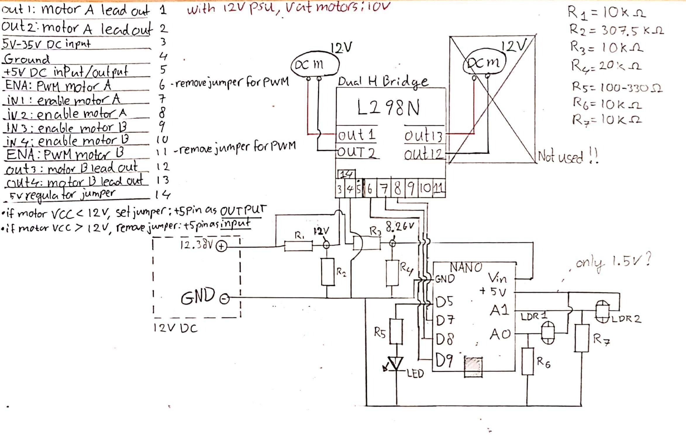
Arduino NANO
L298N dual H-bridge
my logic
when supplying 8.26V to the Vin pin of the NANO, i expected it to go through the 5V regulator and power the IC while also supplying voltage through the 5V pin. for some reason i only get 1.5V out of the 5V pin and can't wrap my head around the reason behind it.
I hope the attached images and code are enough, thank you for your time.
see code below:
//sensor connections
#define ldr_LEFT 0
#define ldr_RIGHT 1
#define led_Warning 5 //this led blinks if both ldr's are 'activated'

//motor connections (L298N)
#define enA 9
#define in1 8
#define in2 7

int fadeLeft = 5;
int fadeRight = 5;

boolean goingLeft = false;
boolean goingRight = false;

void setup() {
  Serial.begin(9600);
  pinMode(led_Warning, OUTPUT);

  // Set all the motor control pins to outputs
  pinMode(enA, OUTPUT);
  pinMode(in1, OUTPUT);
  pinMode(in2, OUTPUT);

  // Turn off motors - Initial state
  digitalWrite(in1, LOW);
  digitalWrite(in2, LOW);
  delay(1000);
}

void loop() {
  directionControl(); //handles direction booleans & warning led
  speedControlLeft();
  speedControlRight();
}

void directionControl() {
  int val_LEFT = analogRead(ldr_LEFT);
  int val_RIGHT = analogRead(ldr_RIGHT);

  if (val_LEFT < 500 && val_RIGHT < 500) {
    goingLeft = false;
    goingRight = false;
    Serial.print("never tickle both armpits\n");
    digitalWrite(led_Warning, HIGH);
    delay(200);
    digitalWrite(led_Warning, LOW);
    delay(200);
    digitalWrite(led_Warning, HIGH);
    delay(200);
    digitalWrite(led_Warning, LOW);
    delay(200);
    digitalWrite(led_Warning, HIGH);
    delay(200);
    digitalWrite(led_Warning, LOW);
    delay(100);
  }

  if (val_LEFT < 500) {
    Serial.print("LEFT LEFT LEFT\t");
    goingLeft = true;
  }
  if (val_RIGHT < 500) {
    Serial.print("RIGHT RIGHT RIGHT\n");
    goingRight = true;
  }
  if (val_LEFT > 600) {
    Serial.print("STOP LEFT\t");
    goingLeft = false;
  }
  if (val_RIGHT > 600) {
    Serial.print("STOP RIGHT\n");
    goingRight = false;
  }
}

void speedControlLeft() {
  if (goingLeft = true) {
    digitalWrite(in1, HIGH);
    digitalWrite(in2, LOW);

    //slowly build up speed
    if (fadeLeft < 255) {
      if (fadeLeft >= 245) {
        fadeLeft = 255;
      }
      else {
        fadeLeft++;
      }
      analogWrite(enA, fadeLeft);
      delay(20);
    }
  }
  //if hand is moved away, initiate braking:
  if (goingLeft = false) {
    fadeLeft = 5;
    // Turn off motors
    digitalWrite(in1, LOW);
    digitalWrite(in2, LOW);
    delay(20);
  }
}

void speedControlRight() {
  if (goingRight = true) {
    digitalWrite(in1, LOW);
    digitalWrite(in2, HIGH);

    //slowly build up speed
    if (fadeRight < 255) {
      if (fadeRight >= 245) {
        fadeRight = 255;
      }
      else {
        fadeRight++;
      }
      analogWrite(enA, fadeRight);
      delay(20);
    }
  }
  //if hand is moved away, initiate braking:
  if (goingRight = false) {
    fadeRight = 5;
    // Turn off motors
    digitalWrite(in1, LOW);
    digitalWrite(in2, LOW);
    delay(20);
  }
}