I have and optical laser sensor which I would like to use using arduino UNO
THe logic of it is if it gets the signal back there is no object between ...and if it doesnt get the signal back there is an object between.
It uses from 10-30VDC...I am powering it with 12V
I would just like to know how should I wire it and the code to use it ... just that the code tells me if there is an object between the sensor and reflecting glass.
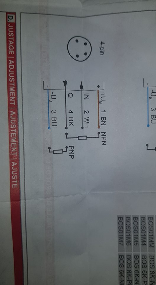
The picture shows an IR reflection beam break sensor.
Measure if there is any voltage on the output wire in both situations (beam detected or not).
Then we know if you have the NPN or PNP version of the sensor.
Leo..
You seem to have the PNP version of the sensor.
Use a voltage divider (two resistors) to drop the 10-12volt output from the sensor (on a 12volt supply) to <=5volt for the Arduino.
Try a 10k resistor between Arduino pin and ground, and a 15k resistor between Arduino pin and sensor output.
Connect sensor ground to Arduino ground.
Leo..
Wawa can you please tell me the schematics of the wiring based on the colors of my wires...
I have lost myself and dont really understand what you meant with the resistors.
Which "Arduino pin" do you intend to use to read the sensor output? That would be the pin in question.
If this is a problem, we strongly recommend that you work through the beginner tutorials, like how to blink an LED, read a pushbutton, read an analog voltage, etc.
Hello
Let me explain this one more time what I am trying to tell you
I have an optical sensor and I want to get output from it on the Arduino.
I just don't know how to wire the sensor and I just want the program to output if there is object in the way or not.
In the picture bellow I wrote what the output is being given to me.
I will be using it for my final exam and I'm kinda in hurry.
The datasheet isn’t very helpful, other than telling you that you’ll need to do some probing to figure the output state under operating conditions.
The Q output of the sensor is what you’re looking for.
It probably swings between the two supply rails (or may be open-collector*).
If you measure between Q and 0V you’ll see the sensor changes.
If it’s pulled ‘high’, you’ll need that voltage divider to get down to 5V
If it’s an *open collector output (or equivalent), you’ll need to use INPUT_PULLUP, or an external +V biasing resistor to see the voltage swing.