Opticoupler Between 24vac & Digital-Pullup Arduino Input

I have designed and implemented an HVAC monitoring solution using an Arduino Mega, a W5100 Ethernet Shield, and a bunch of 24vac relays ... and it's working well.

I'm now designing ver.2 of this, with the hopes of significantly shrinking the project. So moving to a Teensy LC instead of the Arduino Mega, an ESP8266 WIFI module instead of the Ethernet shield, and hoping to use PC817 opticouplers in place of the 24v relays.

My question is around the circuit for the opticouplers. My code is designed to use Digital input pis with the internal pull-up enabled. Right now, my design is setup so when a 24vac HVAC signal wire goes hot, it triggers a 24vac relay which connects the Arduino GND to the digital input pin (with pull-up enabled).

In keeping with this approach, I think I can use a simple component design and connect the GND from the Teensy (or from the Arduino) to pin 4 of the PC817, and simply connect pin 5 of the PC817 directly to the digital input pin of the Teensy (or Arduino) with the internal pull enabled.

I'm looking for confirmation my thinking on this is correct though, as this is new territory for me. My assumption is when the opticoupler's input has no signal, the input pin will be pulled HIGH through the internal pull-up. When the opticoupler's input receives a signal, it should connect to ground and send the input pin to LOW.

So question 1 is .... Do I have the above right?

Question 2 relates to what value resistors to use for the 24vac input to the Opticoupler (R1 and R3 in the attached diagram). I have the PC817 chips here, and did some preliminary testing with 5vdc. a 220ohm resistor drops the voltage to 1.2vdc when the opticoupler's input is connected, and produces a good result on the Opticoupler's output.

So the mA draw looks to be right around 22mA.

If I use 22mA as a load value, and do the math on dropping 24v to 1.2v, I'm getting around a 1036 ohm result. If I change that to 1 kOhm, I get 24mA.

Considering the PC817 seems to be good for up to 30mA (if I'm reading the datasheet correctly), it looks like 1kOhm total resistance is what I want here. So two 500 Ohm resistors in series, just fr added protection.

Question 2 is ... Do I have this calculation right?

Thanks for any input :slight_smile:

An optocoupler driven by AC will turn the output circuit on and off at the AC rate. Is this what you want?

Paul

Paul_KD7HB:
An optocoupler driven by AC will turn the output circuit on and off at the AC rate. Is this what you want?

Paul

Thanks ... Ya, I'm aware it'll cycle at 60Hz. I plan to address it in the code though. Where the signal must be off for so many cycles before the state is updated. A sort of modified debounce approach.

I'm just not sure if my assumptions on the wiring and resistor values are accurate

Stoopalini:
Thanks ... Ya, I'm aware it'll cycle at 60Hz. I plan to address it in the code though. Where the signal must be off for so many cycles before the state is updated. A sort of modified debounce approach.

I'm just not sure if my assumptions on the wiring and resistor values are accurate

No, you have to use the peak value for the 24 volts, which is 1.414 X 24.

Paul

Paul_KD7HB:
No, you have to use the peak value for the 24 volts, which is 1.414 X 24.

Paul

Sorry Paul, I'm not following.

Are you saying I need to use 33.936vac in my calculations instead of 24v? FWIW: The HVAC transformer is outputting 27.7vac.

Stoopalini:
Sorry Paul, I'm not following.

Are you saying I need to use 33.936vac in my calculations instead of 24v? FWIW: The HVAC transformer is outputting 27.7vac.

You are reading RMS values, an average value. You need to use the peak value to correctly compute the series resistor value because the current will also be a peak value. So 27.7 X 1.414 will be the peak value. Be sure the LED in the optoisolator can withstand a peak reverse voltage or else it will only light once!

Paul

Paul_KD7HB:
You are reading RMS values, an average value. You need to use the peak value to correctly compute the series resistor value because the current will also be a peak value. So 27.7 X 1.414 will be the peak value. Be sure the LED in the optoisolator can withstand a peak reverse voltage or else it will only light once!

Paul

Gotcha, makes sense ... thanks!

Isn't there a form of an Opto-Coupler which employs two LEDs, in reverse polarity, so when AC voltage is input, the phototransistor has a light signal on both sides of the AC wave?

If there is such a device, it seems I may have purchased the PC817's a bit premature.

Here's a datasheet link for PC814:

EDIT: you will need a decoupling capacitor on the output to filter the 120Hz pulsations. 0.1uF?

JCA34F:
Here's a datasheet link for PC814:
https://media.digikey.com/pdf/Data%20Sheets/Sharp%20PDFs/PC814X%20Series.pdf
EDIT: you will need a decoupling capacitor on the output to filter the 120Hz pulsations. 0.1uF?

Thanks! So the 814 has the dual LEDs, perfect. Looks like it comes in a 4 channel as well (PC844x), which would be great considering I have 10 24vac inputs I'd like to monitor.

Now the challenge is finding someplace which stocks them. Mouser doesn't, and has a 24,000 minimum order quantity for a special order. Digikey doesn't stock them either .. both places state it as "Obsolete".

Are the PC814/PC844 not made anymore? Wonder if there's a replacement for it ...

LiteOn makes an equivalent, so does Panasonic:

Cross reference:

JCA34F:
LiteOn makes an equivalent, so does Panasonic:
https://optoelectronics.liteon.com/upload/download/DS-70-96-0013/LTV-8X4%20series%20201509.pdf

Perfect, thanks!

I just ordered a few of the 4 channel and a few of the singe channel ones.

For the input signal on these, would a 1k limiting resistor work?

For the input signal on these, would a 1k limiting resistor work?

Hmmm, think I would start with about 5mA thru the LED so 27V / 0.005 = 5400Ω, try 4.7K then 3.3.

JCA34F:
Hmmm, think I would start with about 5mA thru the LED so 27V / 0.005 = 5400Ω, try 4.7K then 3.3.

Thanks again, really appreciate the input.

So a 4.7kOhm 1/4w resistor on the input, and a 0.1uF 50v capacitor on the output side

Would you please take a look at the diagram I attached, to make sure I got this right? I assume the + side of the cap goes to pin #4, which I'm attaching to the Arduino input pin?

JCA34F:
Hmmm, think I would start with about 5mA thru the LED so 27V / 0.005 = 5400Ω, try 4.7K then 3.3.

BTW: 5mA is working well on the PC817. I've tried 1kOhm with 5v, as well as 470Ohm with 3.3v (6.4mA in this case) and it seems to be cool and stable. I also tried a 1k, a 5k, a 10k and even 20k pull up resistance on the output, and it's stable with all of them. The 5v Arduino mega uses 10k pull-up resistors, and I believe the 3.3v Tensy LC uses 4.7k pull-up resistors. So it looks like the internal pull-ups should work well for this, and reduce my component soldering a bit.

I'll test the LTV814 and 844's the same way when they arrive.

Then I'll grab a 24vac power source and test with the capacitor.

Should I be adding a diode to the optocoupler's input? Or is that not needed in my case...

Did you get this working? I have a similar requirement for monitoring a rain sensor. I would appreciate a copy of your final schematic if you got it working.

olddawg:
Did you get this working? I have a similar requirement for monitoring a rain sensor. I would appreciate a copy of your final schematic if you got it working.

Ya, I did get it working. It's been rock solid for 4 months now as well, and still working perfectly.

Here is my final schematic ....

1 Like

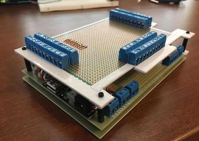
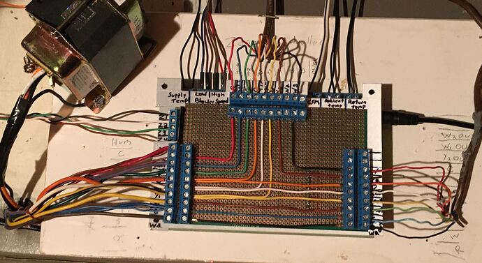
And here's what the final product looks like:

1 Like