Was wondering if this looks reasonable for an opto-isolated RS232 connection. BMS outputs 9600 baud, 5V TTL level. This is just the RS232 part, there will be micro of some sort, connected to the right side of the circuit.
You are confusing RS-232 with a regular serial data stream. RS-232 is a signal with voltages, + and -, from +3 to +25 and -3 to -25 volts, all in relation to a signal ground connection. You will need to use either an purchased adapter or use ICs that are specifically designed for RS-232 to TTL conversion.
@LarryD and @Paul_KD7HB - I agree in the best design that proper RS232 signals would be expected.
But I've been using inverted software serial comms driving RS232 lines with a 5 volt logic output, and reading them with an input with a 22K ohm current limiting resistor.
This was based on some demonstration code I read somewhere. Seemed cheap and easy, and works very well.
I haven't traced any faults to having done that.
So I'd like to hear if and why that is a Bad Idea. I have gone all to the trouble of using, say, the MAX232 chips, but I'm cheap and lazy…
That works for some PC RS232 interfaces, which accept any input of 0V or less as "negative" and any input > 3V as "positive" RS232 signals. It does not work for more conventional RS232 interfaces, which expect negative inputs to be between -5V and about -12V.
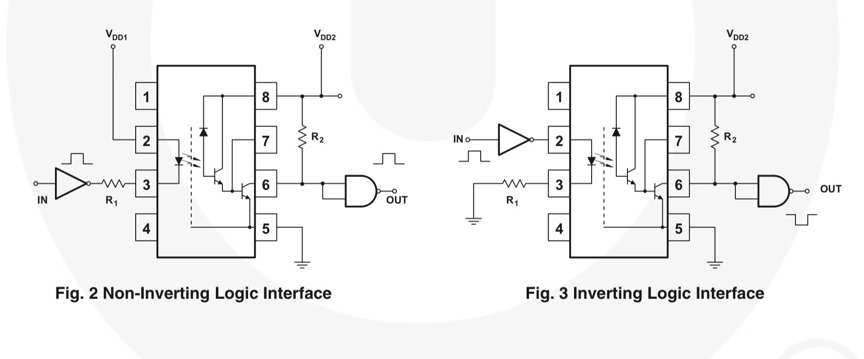
Yes, this NOT true RS232 communication but that's what the manufacturer calls it. I have used a MAX3232 chip to successfully communicate with a GPS module that has a true plus and minus port voltages. Worked perfectly. Only thing I'm not sure about is if my Arduino or ESP processor can handle the inverted logic of the above circuit. But, I guess if I select a non-inverting opto, as suggested by LarryD, then it should be OK.
FYI, this is what I'm trying to communicate with and it must be isolated. The User Manual link shown on this page describes the interface.
I have browsed all the documentation and I see NO indication or warning that the communications must be completely isolated or even a hint. Can you please point us to the requirement?
Paul_KD7HB - A Battery Management System is a pretty complicated device. In my units, there are 8 small leads that come out of it, that are used to balance the individual LiPo cells in my battery pack. The 100A BMS is wired between the system/vehicle ground, and the battery negative post(see image below). The BMS has the ability to disconnect itself from the battery pack, to protect the battery and/or the BMS. If it disconnects, and there are many conditions the BMS monitors that can cause a disconnect, then the vehicle ground is no longer connected to the battery negative post. Internally, the ground connection on the BMS serial comm port is always connected to the negative post on the battery. So, if the battery disconnects, you will have 28 volts between what I call GND_ISO in the above circuit, and the vehicle ground, smoking anything in between !! Overkill Solar offers an accessory, an isolated USB adapter, but their software for that accessory only runs on a PC. I've looked into using an Arduino or ESP in USB Host Mode, but that is a whole 'nother can of worms !!