Overflow in implicit constant conversion [-Woverflow] with Arduino Hexadecimal codes

First let me explain what I am programming. I have created an Arduino Line Follower that also implements using an IR controller and receiver to control its speed and to change lanes between the line it is following. The line follower uses 3 photoresistors as the line sensors, an L298n H-bridge to drive the 2 motors of the robot, and the IR controller and receiver with all components being fixed to a aluminium chassis with nuts bolts and plastic spacers. I wired up the three photoresistors to PWM pins 8, 10, and 6 on the Arduino Nano and I wired up my H-bridge using pins that can be seen in my code below. I also got the Hexadecimal codes for the buttons I was using on the IR controller and wrote the code for using the buttons, obviously using the Hexadecimals I had gotten from the test I had done. When it came to finally testing the code I had written for the line follower with IR control I encountered the warning:

C:\Users\User\OneDrive\Technology\Technology Project\Alpha_Velocita_Mk2_Line_Following\Alpha_Velocita_Mk2_Line_Following.ino:21:16: warning: overflow in implicit constant conversion [-Woverflow]
C:\Users\User\OneDrive\Technology\Technology Project\Alpha_Velocita_Mk2_Line_Following\Alpha_Velocita_Mk2_Line_Following.ino:22:16: warning: overflow in implicit constant conversion [-Woverflow]
C:\Users\User\OneDrive\Technology\Technology Project\Alpha_Velocita_Mk2_Line_Following\Alpha_Velocita_Mk2_Line_Following.ino:23:16: warning: overflow in implicit constant conversion [-Woverflow]
C:\Users\User\OneDrive\Technology\Technology Project\Alpha_Velocita_Mk2_Line_Following\Alpha_Velocita_Mk2_Line_Following.ino:24:16: warning: overflow in implicit constant conversion [-Woverflow]
C:\Users\User\OneDrive\Technology\Technology Project\Alpha_Velocita_Mk2_Line_Following\Alpha_Velocita_Mk2_Line_Following.ino:25:18: warning: overflow in implicit constant conversion [-Woverflow]

These where all the lines in which I had put the Hexadecimals. Here is the actual code:

#include <IRremote.h>
#include <IRremoteInt.h>

//Define the sensor
#define RS 8
#define LS 10
#define MS 6
//Define the right motor
#define LM1 4
#define LM2 5
#define enR 3
//Define the left motor
#define RM1 12
#define RM2 7
#define enL 9

//IR CONTROLLER SETUP//
const int RECV_PIN = 11;
IRrecv irrecv(RECV_PIN);
decode_results results;
const int US = 0xFF629D;  // UP SPEED      
const int DS = 0xFFA857;  //DOWN SPEED
const int LL = 0xFF22DD;  //LEFT LANE
const int RL = 0xFFC23D;  //RIGHT LANE
const int STOP = 0xFF02FD;


//Speed settings for line follower
int speeds[] = {0, 90, 130, 170, 220};
const int SpdMax = sizeof(speeds) / sizeof(int);
int spdIndex;


void setup()
{
  Serial.begin(9600);
  irrecv.enableIRIn();
  pinMode(RS, INPUT);
  pinMode(LS, INPUT);
  pinMode(MS, INPUT);
  
  pinMode(LM1, OUTPUT);
  pinMode(LM2, OUTPUT);
  pinMode(RM1, OUTPUT);
  pinMode(RM2, OUTPUT);
  
  pinMode(enL, OUTPUT);
  pinMode(enR, OUTPUT);

  digitalWrite(enL, HIGH); 
  digitalWrite(enR, HIGH); 

  delay(500);
}

void loop() {
  if(irrecv.decode(&results))  {
    int code = results.value;
    switch (code)  {
    case US:
        if (SpdMax > spdIndex)
            spdIndex++;
        break;

    case DS:
        if (0 < spdIndex)
            spdIndex--;
        break;

    case LL:
        TurnLeft ();
        delay(750);
        lineFollow();
        break;

    case RL:
        TurnRight ();
        delay(750);
        lineFollow();
        break;

    case STOP:
        Stop ();
        break;
    }

    irrecv.resume();
  }
}

//Defining the lineFollow command.
void lineFollow(){
 if((digitalRead(RS)==LOW)&&(digitalRead(LS)==LOW)&&(digitalRead(MS)==HIGH))
  {
    MoveForward();
  }
 if((digitalRead(RS)==HIGH)&&(digitalRead(LS)==HIGH)&&(digitalRead(MS)==HIGH))
  {
    Stop();
  }  
 if((digitalRead(RS)==LOW)&&(digitalRead(LS)==HIGH))
  {
    TurnLeft();
  }
 if((digitalRead(RS)==HIGH)&&(digitalRead(LS)==LOW))
  {
    TurnRight();
  }
 }
  
//Define conditions to move forward
void MoveForward()
{
  digitalWrite(LM1, HIGH);
  digitalWrite(LM2, LOW);
  digitalWrite(RM1, LOW);
  digitalWrite(RM2, HIGH);
  
  analogWrite(enL, speeds[spdIndex]);
  analogWrite(enR, speeds[spdIndex]);
  
  delay(20);
}

//Define conditions to stop
void Stop()
{
  digitalWrite(LM1, LOW);
  digitalWrite(LM2, LOW);
  digitalWrite(RM1, LOW);
  digitalWrite(RM2, LOW);
  
  analogWrite(enL, 0);
  analogWrite(enR, 0);
  
  delay(20);
}

//Define Turn Left
void TurnLeft()
{
  digitalWrite(LM1, HIGH);
  digitalWrite(LM2, LOW);
  digitalWrite(RM1, LOW);
  digitalWrite(RM2, LOW);
  
  analogWrite(enL, speeds[spdIndex]);
  analogWrite(enR, 0);
  
  delay(20);
}

//Define Turn Right
void TurnRight()
{
  digitalWrite(LM1, LOW);
  digitalWrite(LM2, LOW);
  digitalWrite(RM1, LOW);
  digitalWrite(RM2, HIGH);
  
  analogWrite(enL, 0);
  analogWrite(enR, speeds[spdIndex]);
  
  delay(20);
}

If somebody could please help me with this warning / error and tell me why it happened I would appreciate it. I am fairly new to Arduino but have gained some experience by doing this programming. If you notice any other problems or have advice on my code I would also really be thankful. I want to learn as much as I can.
24 into 16 does not go.
Use uint32_t instead

It's simple, luckily. an 'int' type is 16 bits on your platform, you are trying to stuff 32 bit values into it.

Have a look at the IR library and examples. You will see.

Thanks will have a good look!

So I took a look at some examples and that and @anon56112670 was correct in saying to use:

uint32_t

However it seems like the problem has moved further down into my void loop where the Hexadecimals are decoded and implemented in the code. Not exactly sure why this has happened, is that to do with the 'int' type being 16 bits on my system or is it a seperate issue with my code. Here is the error I got:

C:\Users\User\OneDrive\Technology\Technology Project\Alpha_Velocita_Mk2_Line_Following\Alpha_Velocita_Mk2_Line_Following.ino: In function 'void loop()':
C:\Users\User\OneDrive\Technology\Technology Project\Alpha_Velocita_Mk2_Line_Following\Alpha_Velocita_Mk2_Line_Following.ino:62:5: warning: overflow in implicit constant conversion [-Woverflow]
C:\Users\User\OneDrive\Technology\Technology Project\Alpha_Velocita_Mk2_Line_Following\Alpha_Velocita_Mk2_Line_Following.ino:67:5: warning: overflow in implicit constant conversion [-Woverflow]
C:\Users\User\OneDrive\Technology\Technology Project\Alpha_Velocita_Mk2_Line_Following\Alpha_Velocita_Mk2_Line_Following.ino:72:5: warning: overflow in implicit constant conversion [-Woverflow]
C:\Users\User\OneDrive\Technology\Technology Project\Alpha_Velocita_Mk2_Line_Following\Alpha_Velocita_Mk2_Line_Following.ino:78:5: warning: overflow in implicit constant conversion [-Woverflow]
C:\Users\User\OneDrive\Technology\Technology Project\Alpha_Velocita_Mk2_Line_Following\Alpha_Velocita_Mk2_Line_Following.ino:84:5: warning: overflow in implicit constant conversion [-Woverflow]

Which corresponds to here in the code:

void loop() {
  if(irrecv.decode(&results))  {
    int code = results.value;
    switch (code)  {
    case US:
        if (SpdMax > spdIndex)
            spdIndex++;
        break;

    case DS:
        if (0 < spdIndex)
            spdIndex--;
        break;

    case LL:
        TurnLeft ();
        delay(750);
        lineFollow();
        break;

    case RL:
        TurnRight ();
        delay(750);
        lineFollow();
        break;

    case STOP:
        Stop ();
        break;
    }

    irrecv.resume();
  }
}

Realised my silly mistake it is ok thanks for your help!

1 Like

Is there any reason now after solving that mistake that the buttons shouldn't at least start the turn left and turn right when I press these buttons on the controller. Trying to figure out if I have a hardware or software issue at this stage. Everything in the code seems right but I am wondering why I can't turn right or left when I press the buttons that correspond to these directions of movement. I just want to make sure that this is a software or hardware issue as then I can continue problem solving. Here is the code I would appreciate if anyone could highlight any problems that might be causing this not to work:

#include <IRremote.h>
#include <IRremoteInt.h>

//Define the sensor
#define RS 8
#define LS 10
#define MS 6
//Define the right motor
#define LM1 4
#define LM2 5
#define enR 3
//Define the left motor
#define RM1 12
#define RM2 7
#define enL 9

//IR CONTROLLER SETUP//
const int RECV_PIN = 11;
IRrecv irrecv(RECV_PIN);
decode_results results;
const  uint32_t US = 0xFF629D;  // UP SPEED      
const uint32_t DS = 0xFFA857;  //DOWN SPEED
const uint32_t LL = 0xFF22DD;  //LEFT LANE
const uint32_t RL = 0xFFC23D;  //RIGHT LANE
const uint32_t STOP = 0xFF02FD;


//Speed settings for line follower
int speeds[] = {0, 90, 130, 170, 220};
const int SpdMax = sizeof(speeds) / sizeof(int);
int spdIndex;


void setup()
{
  Serial.begin(9600);
  irrecv.enableIRIn();
  pinMode(RS, INPUT);
  pinMode(LS, INPUT);
  pinMode(MS, INPUT);
  
  pinMode(LM1, OUTPUT);
  pinMode(LM2, OUTPUT);
  pinMode(RM1, OUTPUT);
  pinMode(RM2, OUTPUT);
  
  pinMode(enL, OUTPUT);
  pinMode(enR, OUTPUT);

  digitalWrite(enL, HIGH); 
  digitalWrite(enR, HIGH); 

  delay(500);
}

void loop() {
  if(irrecv.decode(&results))  {
    uint32_t code = results.value;
    switch (code)  {
    case US:
        if (SpdMax > spdIndex)
            spdIndex++;
        break;

    case DS:
        if (0 < spdIndex)
            spdIndex--;
        break;

    case LL:
        TurnLeftIR ();
        delay(750);
        lineFollow();
        break;

    case RL:
        TurnRightIR ();
        delay(750);
        lineFollow();
        break;

    case STOP:
        Stop ();
        break;
    }

    irrecv.resume();
  }
}

//Defining the lineFollow command.
void lineFollow(){
 if((digitalRead(RS)==LOW)&&(digitalRead(LS)==LOW)&&(digitalRead(MS)==HIGH))
  {
    MoveForward();
  }
 if((digitalRead(RS)==HIGH)&&(digitalRead(LS)==HIGH)&&(digitalRead(MS)==HIGH))
  {
    Stop();
  }  
 if((digitalRead(RS)==LOW)&&(digitalRead(LS)==HIGH))
  {
    TurnLeft();
  }
 if((digitalRead(RS)==HIGH)&&(digitalRead(LS)==LOW))
  {
    TurnRight();
  }
 }
  
//Define conditions to move forward
void MoveForward()
{
  digitalWrite(LM1, HIGH);
  digitalWrite(LM2, LOW);
  digitalWrite(RM1, LOW);
  digitalWrite(RM2, HIGH);
  
  analogWrite(enL, speeds[spdIndex]);
  analogWrite(enR, speeds[spdIndex]);
  
  delay(20);
}

//Define conditions to stop
void Stop()
{
  digitalWrite(LM1, LOW);
  digitalWrite(LM2, LOW);
  digitalWrite(RM1, LOW);
  digitalWrite(RM2, LOW);
  
  analogWrite(enL, 0);
  analogWrite(enR, 0);
  
  delay(20);
}

//Define Turn Left
void TurnLeft()
{
  digitalWrite(LM1, HIGH);
  digitalWrite(LM2, LOW);
  digitalWrite(RM1, LOW);
  digitalWrite(RM2, LOW);
  
  analogWrite(enL, speeds[spdIndex]);
  analogWrite(enR, 0);
  
  delay(20);
}

//Define Turn Right
void TurnRight()
{
  digitalWrite(LM1, LOW);
  digitalWrite(LM2, LOW);
  digitalWrite(RM1, LOW);
  digitalWrite(RM2, HIGH);
  
  analogWrite(enL, 0);
  analogWrite(enR, speeds[spdIndex]);
  
  delay(20);
}

//Define Turn Left for IR Turn Button Left.
void TurnLeftIR()
{
  digitalWrite(LM1, HIGH);
  digitalWrite(LM2, LOW);
  digitalWrite(RM1, LOW);
  digitalWrite(RM2, LOW);
  
  analogWrite(enL, 230);
  analogWrite(enR, 0);
  
  delay(20);
}

//Define Turn Right for IR Turn Button Right.
void TurnRightIR()
{
  digitalWrite(LM1, LOW);
  digitalWrite(LM2, LOW);
  digitalWrite(RM1, LOW);
  digitalWrite(RM2, HIGH);
  
  analogWrite(enL, 0);
  analogWrite(enR, 230);
  
  delay(20);
}

How about some debug prints, to let your code tell you what it is doing?

That is normally done by writing hardware specific test sketches, that have no unrelated code to introduce uncertainty.

e.g.

button test sketch
motor test sketch

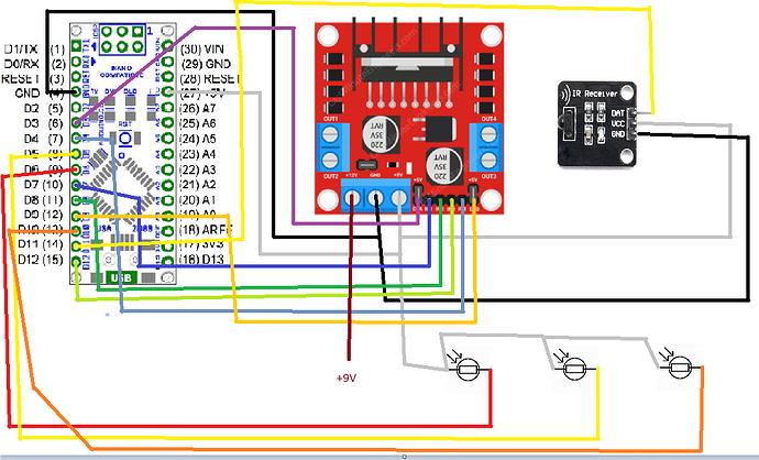
You flaunted the forum guidelines and did not post a schematic. Do you have pull up or down resistors on the button switches? Please post a wiring diagram or schematic.

1 Like

If those are LDRs on D6,D10 and D5, then you have wired them incorrectly. They need a current source resistor to make a voltage divider. See any LDR input circuit via Google.

Same thing, if they are switches not LDR's. If you made that mistake, please research electronics symbols. Consult the Arduino switch examples and tutorials to learn how to connect and read a switch.

1 Like

OK, but shouldn't my motors at least run now when I press the buttons for lane changing with that circuit even though I haven't wired up the LDR's yet. I am talking about this part of the code:

 case LL:
        TurnLeftIR ();
        delay(750);
        lineFollow();
        break;

    case RL:
        TurnRightIR ();
        delay(750);
        lineFollow();
        break;

    case STOP:
        Stop ();
        break;
    }

I refuse to talk about anything that is not in the diagram. Please update it to accurately reflect your physical circuit, or my help will end with this post.

You have:
#define RS 8
#define LS 10
#define MS 6

The wiring shows 5, 6, 10.


For an LDR, add a sourcing resistor, feed the junction to an analog input pin, use analogRead then determine if there is reflection or not.

The position of LDR and 10k resistor can be reversed.

Sorry yah that is an older version of code as I realised one of the sensors wasn't on a PWM pin so I changed it around. I will take a look at everything people have told me too now and try and fix any mistakes.

So are you telling me, both your posted code and schematic were wrong, you knew that and didn't tell us?

No I only changed the problems after I posted it and got a reply back. The PWM port was just a problem I noticed when making the 'uint32_t' fix to the code, it was a silly mistake and obviously must have gotten mixed up during looking at my circuit or something. I would only ask genuine problems I can't figure out myself on this forum.

Are we up to date with everything now, full and actual code and schematic?

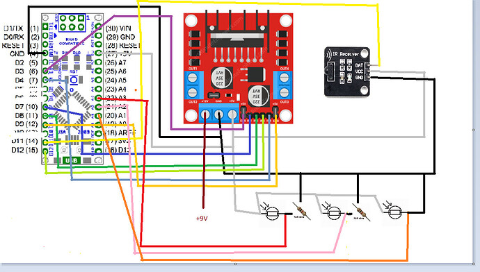
Yes, here is the fixed schematic from what I looked at:

And here is the code to match:

#include <IRremote.h>
#include <IRremoteInt.h>

//Define the sensor
#define RS A3
#define LS A1
#define MS A2
//Define the right motor
#define LM1 4
#define LM2 8
#define enR 3
//Define the left motor
#define RM1 12
#define RM2 7
#define enL 9

//IR CONTROLLER SETUP//
const int RECV_PIN = 11;
IRrecv irrecv(RECV_PIN);
decode_results results;
const  uint32_t US = 0xFF629D;  // UP SPEED      
const uint32_t DS = 0xFFA857;  //DOWN SPEED
const uint32_t LL = 0xFF22DD;  //LEFT LANE
const uint32_t RL = 0xFFC23D;  //RIGHT LANE
const uint32_t STOP = 0xFF02FD;


//Speed settings for line follower
int speeds[] = {0, 90, 130, 170, 220};
const int SpdMax = sizeof(speeds) / sizeof(int);
int spdIndex;


void setup()
{
  Serial.begin(9600);
  irrecv.enableIRIn();
  pinMode(RS, INPUT);
  pinMode(LS, INPUT);
  pinMode(MS, INPUT);
  
  pinMode(LM1, OUTPUT);
  pinMode(LM2, OUTPUT);
  pinMode(RM1, OUTPUT);
  pinMode(RM2, OUTPUT);
  
  pinMode(enL, OUTPUT);
  pinMode(enR, OUTPUT);

  digitalWrite(enL, HIGH); 
  digitalWrite(enR, HIGH); 

  delay(500);
}

void loop() {
  if(irrecv.decode(&results))  {
    uint32_t code = results.value;
    switch (code)  {
    case US:
        if (SpdMax > spdIndex)
            spdIndex++;
        break;

    case DS:
        if (0 < spdIndex)
            spdIndex--;
        break;

    case LL:
        TurnLeftIR ();
        delay(750);
        lineFollow();
        break;

    case RL:
        TurnRightIR ();
        delay(750);
        lineFollow();
        break;

    case STOP:
        Stop ();
        break;
    }

    irrecv.resume();
  }
}

//Defining the lineFollow command.
void lineFollow(){
 if((digitalRead(RS)==LOW)&&(digitalRead(LS)==LOW)&&(digitalRead(MS)==HIGH))
  {
    MoveForward();
  }
 if((digitalRead(RS)==HIGH)&&(digitalRead(LS)==HIGH)&&(digitalRead(MS)==HIGH))
  {
    Stop();
  }  
 if((digitalRead(RS)==LOW)&&(digitalRead(LS)==HIGH))
  {
    TurnLeft();
  }
 if((digitalRead(RS)==HIGH)&&(digitalRead(LS)==LOW))
  {
    TurnRight();
  }
 }
  
//Define conditions to move forward
void MoveForward()
{
  digitalWrite(LM1, HIGH);
  digitalWrite(LM2, LOW);
  digitalWrite(RM1, LOW);
  digitalWrite(RM2, HIGH);
  
  analogWrite(enL, speeds[spdIndex]);
  analogWrite(enR, speeds[spdIndex]);
  
  delay(20);
}

//Define conditions to stop
void Stop()
{
  digitalWrite(LM1, LOW);
  digitalWrite(LM2, LOW);
  digitalWrite(RM1, LOW);
  digitalWrite(RM2, LOW);
  
  analogWrite(enL, 0);
  analogWrite(enR, 0);
  
  delay(20);
}

//Define Turn Left
void TurnLeft()
{
  digitalWrite(LM1, HIGH);
  digitalWrite(LM2, LOW);
  digitalWrite(RM1, LOW);
  digitalWrite(RM2, LOW);
  
  analogWrite(enL, speeds[spdIndex]);
  analogWrite(enR, 0);
  
  delay(20);
}

//Define Turn Right
void TurnRight()
{
  digitalWrite(LM1, LOW);
  digitalWrite(LM2, LOW);
  digitalWrite(RM1, LOW);
  digitalWrite(RM2, HIGH);
  
  analogWrite(enL, 0);
  analogWrite(enR, speeds[spdIndex]);
  
  delay(20);
}

//Define Turn Left for IR Turn Button Left.
void TurnLeftIR()
{
  digitalWrite(LM1, HIGH);
  digitalWrite(LM2, LOW);
  digitalWrite(RM1, LOW);
  digitalWrite(RM2, LOW);
  
  analogWrite(enL, 230);
  analogWrite(enR, 0);
  
  delay(20);
}

//Define Turn Right for IR Turn Button Right.
void TurnRightIR()
{
  digitalWrite(LM1, LOW);
  digitalWrite(LM2, LOW);
  digitalWrite(RM1, LOW);
  digitalWrite(RM2, HIGH);
  
  analogWrite(enL, 0);
  analogWrite(enR, 230);
  
  delay(20);
}

Thank you very much. Can we please also have an updated summary of the problem?