Hi, currently i have bought a PCA9685 controller online to use with my arduino mega, and i tried to follow this tutorial online:
however the code i tried didn't work for me and none of the servos moved.
I used 24 MG90s 360 continuous servos connected to 2 PCA9685 controllers, with the i2c addresses of 0x40 and 0x41.
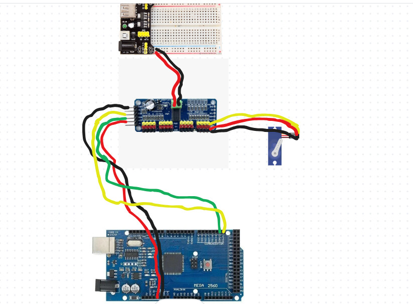
OK, go back to a simpler situation like the one in your wiring diagram, or even simpler: connect a single PCA9685 board to your Arduino. Nothing else. No servo, no external power supply.
Now run an I2Cscanner sketch (see e.g. here I2CScanner - Arduino Reference) and verify if the PCA9685 module is detected. If so, proceed and connect one stepper, and try to get that to move. If not, review your connections.
24 servos? Check to see whether you've still got 5V on the centre pin of one of the servo connector. If you've got clone boards with the tiny SOT23 reverse polarity protection MOSFET, you may have blown it.
Also, one of those little breadboard power supplies can't supply enough amperage to run even 2 or 3 servos for any length of time, let alone 24.
This may help you in your design:
Gil's Crispy Critter Rules, they apply to processor hardware:
Rule #1. A Power Supply the Arduino is NOT!
Rule #2. Never Connect Anything Inductive (motor, speaker) to an Arduino!
Rule #3 Don't connecting or disconnecting wires with power on.
Rule #4 Do not apply power to any pin unless you know what you are doing.
Rule #5 Do not exceed maximum Voltages.
LaryD's Corollary's
Coro #1 when first starting out, add a 220R resistor in series with both Input and Output pins.
Coro #2 buy a DMM (Digital Multi-meter) to measure voltages, currents and resistance. Violating these rules tends to make crispy critters out of Arduinos.
Hint: It is best to keep the wires under 25cm/10" for good performance.
Okay, i tried changing the power supply from the breadboard to a 5v power supply, and now it works
atleast for the first PCA9685 board, the second PCA9685 board used to work on a few motors, but now it had stopped working on all servos on the second PCA9685 board, and all it just makes is a ticking sound for each servo that has been sent a signal.
Here is my code:
How about an updated schematic + photos of the new wiring?
Also, consider testing the PCA9685 outputs with LEDs (and series resistors). This removes the complication of a power supply issue for the motors, for instance.
Can you please post a copy of your circuit, a picture of a hand drawn circuit in jpg, png?
Hand drawn and photographed is perfectly acceptable.
Please include ALL hardware, power supplies, component names and pin labels.
Sorry, no.
Start with a blank piece of PAPER and draw with pen(cil) and ruler, then post a picture of it.
Please include ALL hardware, power supplies, component names and pin labels.
Take your time. use gnd symbols for gnd connections.
Start by removing one of the PCA modules. Replace the servo with a LED + series resistor. Leave out the additional 5V power supply and only connect 5V from the UNO to the PCA module. Test a few PWM channels this way. Now replace the PCA module with the other one. Test again. This will show whether your PCA's work.
Now connect both PCA's and determine with LEDs if they still work.
In a parallel test, replace the LED with a single of those MG90 servos and see if it works. For a single MG90 you don't need an external 5V PSU; they'll run OK from just the UNO 5V.
(I'm assuming you're using MG90 servos because those are shown in your earlier pictures; please verify this is the case - after all, you also showed an UNO in your earlier illustrations that turned out to be an UNO WiFi. Please try to be complete & consistent in your circuit descriptions. Information that may appear irrelevant to you may be crucial in reality.)
The idea of the tests above is to isolate the problem to a specific component or combination. You could do any kind of variation on the theme of systematic testing where you eliminate variables. Due to the number of components involved, you have to start small since you'll otherwise have too many candidate causes for a problem.
Systematically track/log/describe your observations and see if you can find a pattern.
and when i tried plugging back in the PCA9685, the I2C LCD had stopped working properly. when i tried using the I2CScanner, it was stuck on ---Scan Started---
and didn't continue. I tried to check if the SDA and SCL pins were connected properly, and tried switching them to the A14 and A15 pins of the Arduino Mega, however it still didn't work.
I've merged your two topics on the same subject. @markyrider, why did you start a new topic? It's considered cross-posting and it wastes people's time.
What happens when you disconnect the PCA9685 modules again? Does the scanner find the LCD?
Those are not the I2C pins. There is a second set of pins for I2C on pins 20 and 21; those are in parallel with the pins marked SDA/SCL so unless you physically damaged the board I do not expect improvements.
I tried disconnecting the PCA9685 SCL and SDA pins, and the lcd works again, and the scanner detects it, however when i plug in back the SCL and SDA pins of the PCA9685, the scanner doesn't find anything and is stuck.
Before when the PCA9685 and LCD modules worked fine together, the I2CScanner managed to find their addresses:
LCD: 0x27
PCA9685 Board 1: 0x40
PCA9685 Board 2: 0x41
Consider that one (or both) of the PCA9685 modules might be faulty. If it is one, it should be easy to determine by only using one, run the scanner, swap them and run the scanner.
@markyrider I still recommend performing the test above.
You'll do yourself a service by removing the wire spaghetti from the machine you're building and transferring it to a desk where you have a computer/laptop. Then use the desktop to do the development/prototyping of the control systems. Only transfer to the machine once everything works.
At a later stage you may have to consider the problems associated with running long wires in a potentially noisy (electrically speaking) environment. But we'll get to that (much) later.
Ok, i tried removing the PCA9685 modules and other components and tested them individually on a table using an LED, the LEDs worked fine, so are the motors when the PCA9685 modules are individually used. However when i tried connecting the two modules together, the second one connected (the one with the address 0x41), usually doesn't function normally and it always made the servos make a ticking sound. I tried testing the servos connected on PCA9685 0x41 to PCa9685 0X40, and they worked fine, just not on the second board when they're connected together.
OK, so you can confirm that the PCA with the 0x41 address works fine if it's connected by itself, also with a servo connected? The problems start only if you add the PCA with 0x40 to the system? Does the problem arise immediately if the 0x40 PCA is connected without any servos (so only ONE servo connected to the 0x41 PCA)? Or does it take the addition of more servos before the problems start?
Yes, i can confirm, the 0x41 and 0x40 PCA9685 boards works (individually) with a servo connected. The 0x41 PCA9685 board only doesn't work once it is connected to the 0x40 PCA9685. I tried connecting both of the PCA9685 boards with only ONE servo for each board while testing, and also one without a servo in one of the boards as well, and i confirm the 0x41 PCA doesn't work at all when chained with the first (0x40) PCA board, only when they are individual