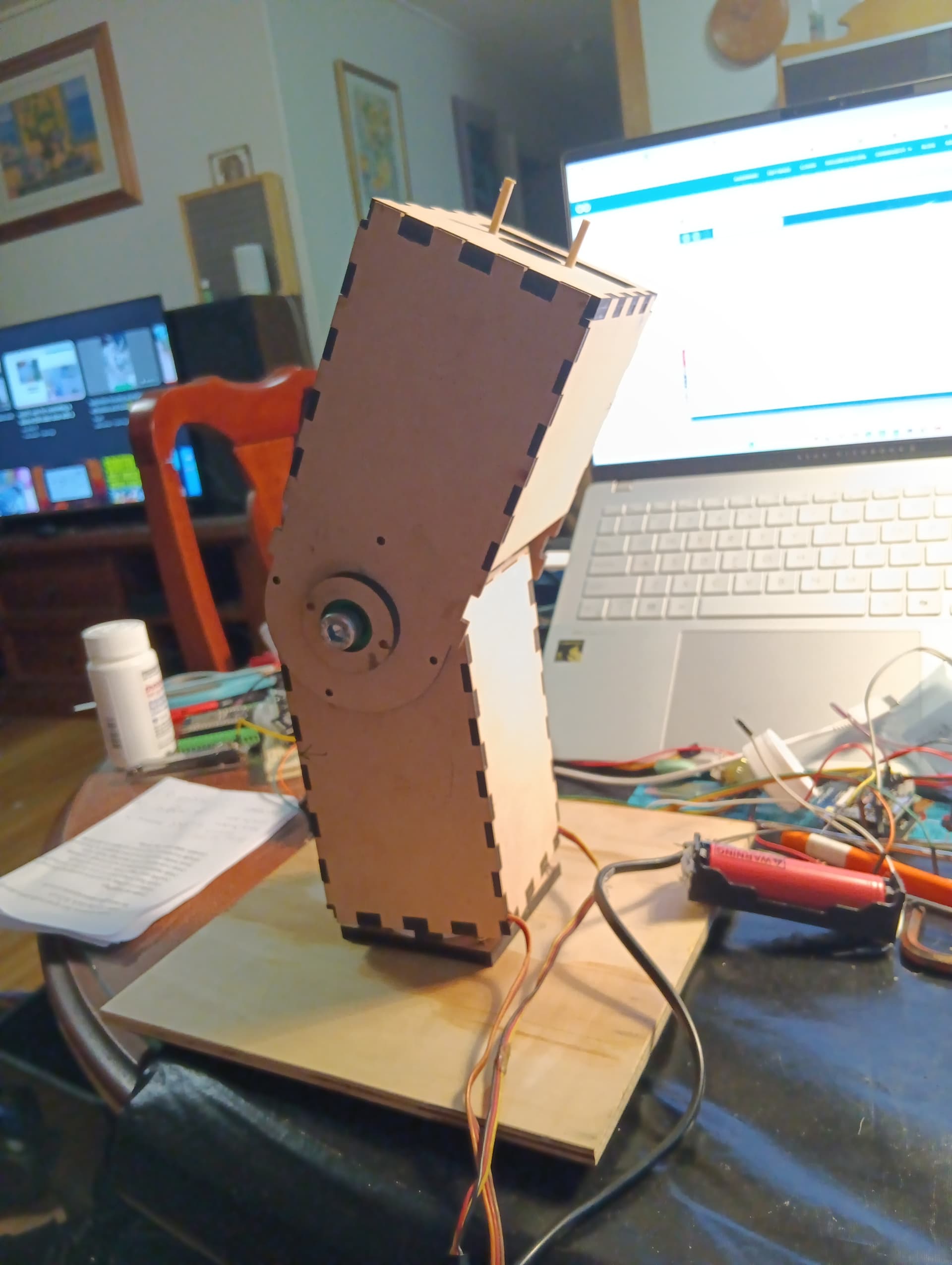
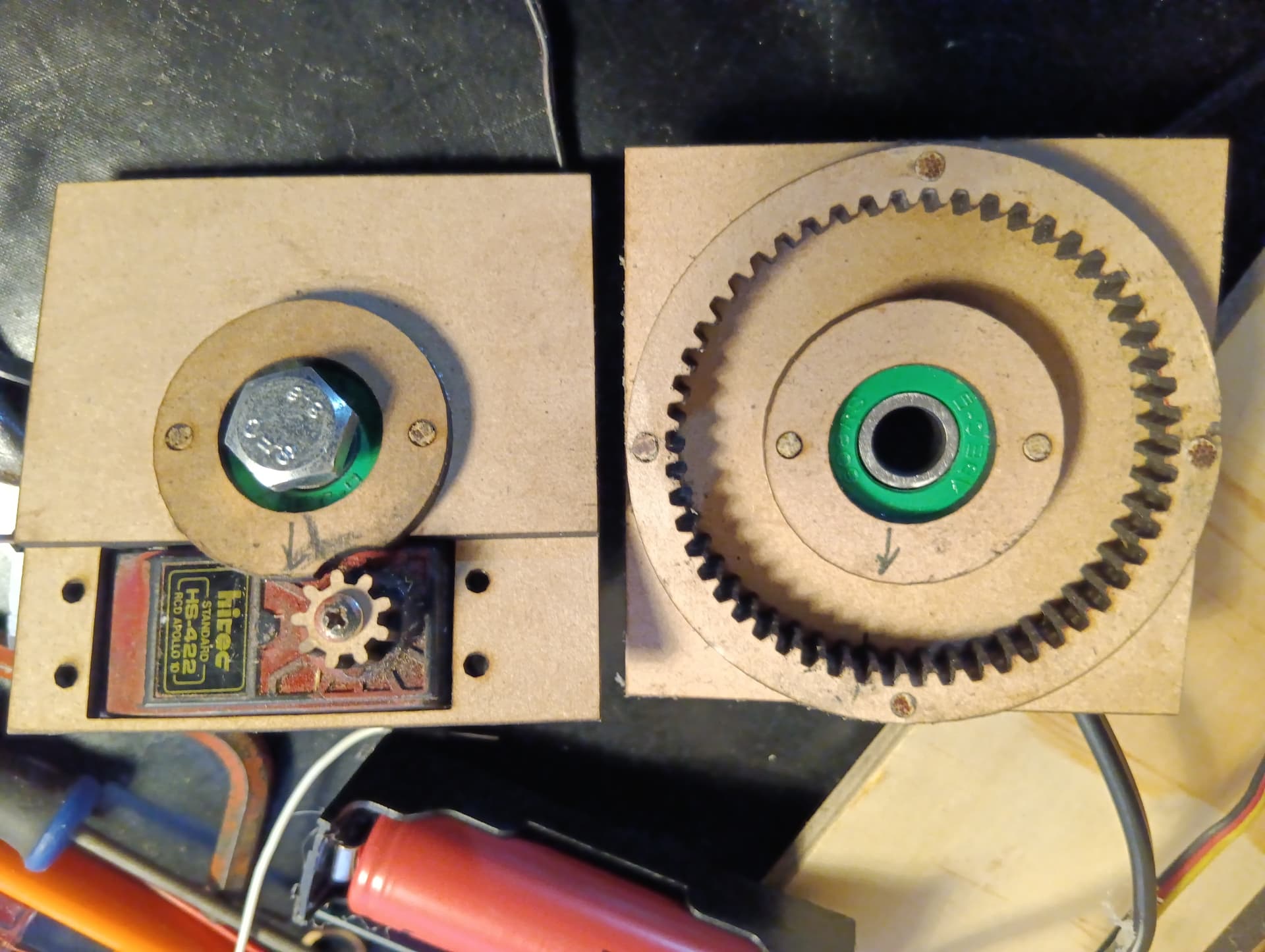
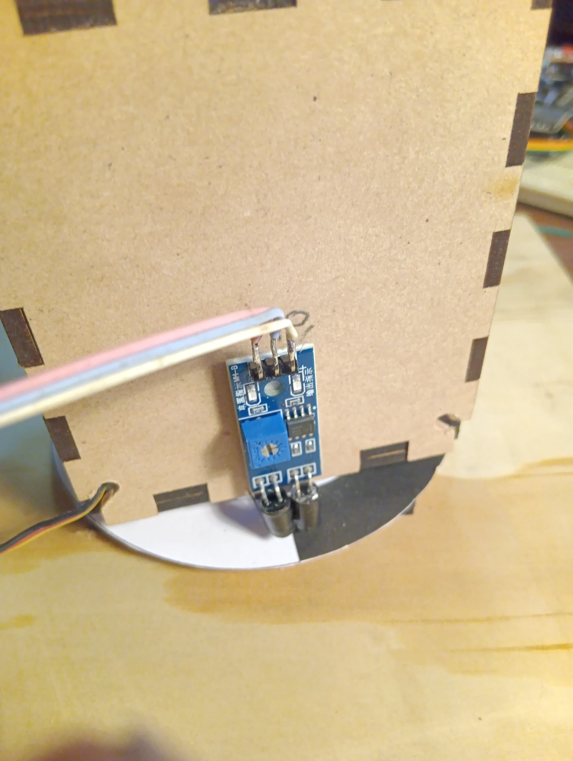
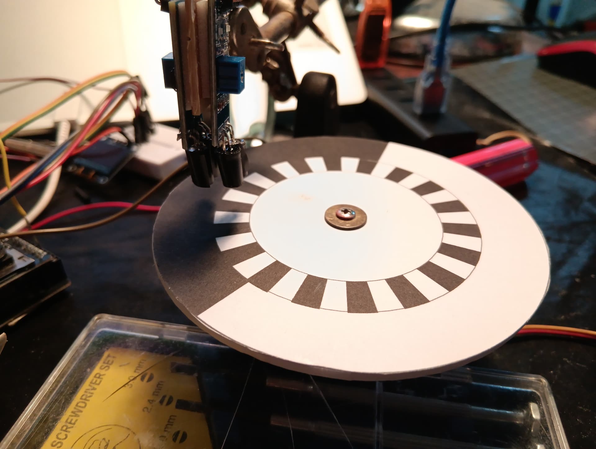
I have designed and Laser cut MDF parts to build Robot arm/autonimous Sentinal. most inexpensive arms seem flimsy and jerky. My design has reduction gears 70 by 70mm + square arms and is using servos modified to be 360 degree. I am designing a position sensor using cheep IR crash avoidance sensors for limit switch and degree counting 10degree. The problem i am a very newby to code writing I usually can cut and paste. but I want to use the PCA9685 I2c Controller but am having trouble finding a suitable sketch using Millis. Using delay the program blocks the IR modules which needs to monitor continuosly. any suggestion for a code download would be apprecieated. at present I only need one servo for calibration and testing position sensing.
The PCA9685 is almost certainly irrelevant to your problem
You are not going to find a sketch that does exactly what you want. You would be better off learning to use millis() for non blocking timing.
See Using millis() for timing. A beginners guide, Several things at the same time and the BlinkWithoutDelay example in the IDE
Hi bob i have been doing research and trying things for 2 days posting here I was hoping for a short cut @ 70 time is important.
If you have a sketch that uses delay() then I suggest that you post it and explain what you would like it to do
Van Inask what your level of knowledge is with microcontrollers, motor drivers etc ?
What are your motors, drivers and power source.
Do you have any diagrams or schematics so far ?
I would like to give you the hint to read and learn the example "Blink Without Delay".
Try to write down that code by heart.
I bet you can do it in 2h.
When you have understood "Blink Without Delay" - you will be able to apply that concept for any non blocking time control you need.
This is my very messed up code with lots of fails.
at present bit is continually monitoring the ir sensor and spinning the servo.
but when i try to use
0= clockwise rotation, 90 = stop 179 = Counter clockwise.
it Blocks the IR . the IR will be the L.R limit and also second IR will read low high and advise LH or RH limit.
/* PCA9685ServoV4
 *  26/12/23
 *
 This sketch is controlling 2 servos, one on pin 0 the 2nd on pin 3
 *
 * PCA9685 Board with MG90 servo
 *
 *
 *
SDA/SCL connections

Arduino UNO: A4 (SDA), A5 (SCL)
Arduino Mega 2560: 20 (SDA), 21 (SCL)
ESP32: 21(SDA), 22 (SCL)

 */


#include "Wire.h"
#include "Adafruit_PWMServoDriver.h"
int signalPin = 8;
const long eventTime_1_LDR = 1000; //in ms

// called this way, it uses the default address 0x40
Adafruit_PWMServoDriver pwm = Adafruit_PWMServoDriver();
// you can also call it with a different address you want
//Adafruit_PWMServoDriver pwm = Adafruit_PWMServoDriver(0x41);
// you can also call it with a different address and I2C interface
//Adafruit_PWMServoDriver pwm = Adafruit_PWMServoDriver(0x40, Wire);

unsigned long currentMillis;//Holds the current board time in milliseconds


#define USMIN  600 // This is the rounded 'minimum' microsecond length based on the minimum pulse of 150
#define USMAX  2400 // This is the rounded 'maximum' microsecond length based on the maximum pulse of 600
#define SERVO_FREQ 50 // Analog servos run at ~50 Hz updates

// our servos
const int servo0 = 0;
const int servo3 = 3;
unsigned long previousTime_1 = 0;
unsigned long previousTime_2 = 0;

void setServoPos(int servo, int pos){
  //This first bit of code makes sure we are not trying to set the servo outside of limits
  int sendPos;
  if(pos > 179){
    pos = 179;
  }
  if(pos < 0){
    pos = 0;
  }
  sendPos = USMIN + ((USMAX - USMIN)/180 * pos);
  if(servo > -1 && servo < 16){//only try to move valid servo addresses
    pwm.writeMicroseconds(servo, sendPos);

    unsigned long previousTime_1 = 0;
    unsigned long previousTime_2 = 0;

  }
}

void setup() {
  Serial.begin(9600);
  //Serial.println("PCA9685ServoV4");
  pinMode(signalPin, INPUT);// set signalPin as input

  pwm.begin();
  pwm.setOscillatorFrequency(27000000);
  pwm.setPWMFreq(SERVO_FREQ);  // Analog servos run at ~50 Hz updates
  delay(10);
}

void loop() {

/* Updates frequently */
  unsigned long currentTime = millis();


  //if ( currentTime - previousTime_1 >= 5000UL) {
  //setServoPos(servo0,179);//0 Degrees
  //Update the timing for the next event*/
 //previousTime_1 = currentTime;}

  //if ( currentTime - previousTime_1>= 500UL) {
  //setServoPos(servo3,0);//0 Degrees
  // Update the timing for the next event*/
  //previousTime_1 = currentTime;}


 // if(currentMillis > 7000){setServoPos(servo0,0);}
//if(currentMillis > 10000){setServoPos(servo0,179);}
 // currentMillis = millis();
 //setServoPos(servo0,90);//90 degrees
  //delay(500);
  //setServoPos(servo0,);//179 degrees
 // delay(6000);
  //setServoPos(servo0,90);//90 degrees
  //delay(500);


   int detect = digitalRead(signalPin);// read obstacle status and store it into "detect"
  if(detect == LOW){

   Serial.println("Obastacle on the way");
  }else{

   Serial.println("All clear");}
   {
    //setServoPos(servo0,0);//0 Degrees
    //delay(5000);
   // setServoPos(servo0,90);//90 degrees
    //delay(2000);
    //setServoPos(servo0,179);//179 degrees
    //delay(5000);}

}}
I have built a gel blaster sentinal following jonathans video. And code.

Do you understand that code ?
Could you write (any) of it by yourself ?
I definitely could not write it i have a basic understanding.
i don't see how that is possible in the code in post #8.
once i remove all the comments, i don't see any calls to setServoPos(). All i see is code that configures the servo, named pwm and code that checkd if the signalPin is LOW
i would expect to see some way of executing commands to drive the servo clockwise, CW, or CCW and continually check if the IR sensor becomes active and set the servo to 90 or 1.5 msec so that it stops
most experience developer start small, in this case,
- some way of recognizing commands, either switches or serial monitor commands
- simple tests to make the servo: Stop, move CW and CCW
- test of the IR sensor
then start combining this understanding into a more complete program that does something.
when i work on mobile robots, the one thing i want to avoid it the robot taking off like a jack rabbit and crashing into the wall
The last commented out section with delay was working but blocked most of the reads from pin 8.
I have another program that works on an esp32 but uses Lan buttons for control on a mearm. I intended trying it tomorrow.
I have gone to a simpler code Joystick controll rotation of servo.
interupt function to stop rotation of servo but just testing with a blue led.but must be missing something.
#include <Servo.h>

Servo servo1;
Servo servo2;
int joyX = A0;
int joyY = A1;        //if in centre is not stopped adjust calibration pot.
int signalPin1 = 13;  // angleTrigger Remember to connect your input to a hardware interrupt capable pin!
int blueLED = 2;


volatile int signalState;
int servoVal;

// ISR function
void buttonInterrupt() {
  signalState = digitalRead(signalPin1);
  if (signalState == LOW) {       // Button pressed!
    digitalWrite(blueLED, HIGH);  // Turn on blue LED
  }
  if (signalState == HIGH) {     // Button not pressed!
    digitalWrite(blueLED, LOW);  // Keep blue LED off
  }
}


void setup() {
  pinMode(blueLED, OUTPUT);
  servo1.attach(3);
  servo2.attach(5);
  // open the serial port at 9600 bps:
  Serial.begin(9600);
}

void loop() {
  // read the analog input on pin 0:
  signalState = digitalRead(signalPin1);
  Serial.println(signalState);

  // servoVal = analogRead(joyX);
  // servoVal = map(servoVal, 0, 1023, 0, 180);
  // servo1.write(servoVal);

  servoVal = analogRead(joyY);
  servoVal = map(servoVal, 0, 1023, 70, 180);
  servo2.write(servoVal);
  delay(15);
}
don't know how you can test servo control using an LED.
presumably setting the servo to 90 deg or 1.5 msec stops a continuous servo from rotating. something > 90 causes it to rotate in one direction and < 90 the other direction.
you can test with using a joystick but would need to set the servo to exactly 90 when it is close to center, 90 +/- 20 deg.
otherwise i suggest you use button switches that set the servo to 180 or 0 deg and 90 otherwise. serial commands can like wise be used
Thanks for the input
step 1. I was just using the led to test the interupt. which was not working.
It looks like I missed a piece of code. I have updated code and
I will test tonight.
Step 2 Once I get the interupt working I am using an IR Sensor to interupt the Rotation By writing 90 Stop to the servo.
Step 3 then read the second IR state to find LH or RH limit.
Step 4 second function My second IR sensor is reading 10 degree change state. 0 and 1
Step 4.5 working out the degree and recording.
Step 5 I intend having a two buttons one to calibrate safe sweep and a second to Home 1/2 sweep angle.
Step 6 when I eventually get all that working implement in my Laser cut Robotarm / Sentinal.
Servo servo1;
Servo servo2;
int joyX = A0;
int joyY = A1;        //if in centre is not stopped adjust calibration pot.
int signalPin1 = 13;  // angleTrigger Remember to connect your input to a hardware interrupt capable pin!
int blueLED = 2;


volatile int signalState;
int servoVal;

// ISR function
void buttonInterrupt() {
  signalState = digitalRead(signalPin1);
  if (signalState == LOW) {       // Button pressed!
    digitalWrite(blueLED, HIGH);  // Turn on blue LED
  }
  if (signalState == HIGH) {     // Button not pressed!
    digitalWrite(blueLED, LOW);  // Keep blue LED off
  }
}


void setup() {
  pinMode(blueLED, OUTPUT);
  servo1.attach(3);
  servo2.attach(5);
  // open the serial port at 9600 bps:
  Serial.begin(9600);
  attachInterrupt(digitalPinToInterrupt(signalPin1), buttonInterrupt, CHANGE);
}

void loop() {
  // read the analog input on pin 0:
  signalState = digitalRead(signalPin1);
  Serial.println(signalState);

  // servoVal = analogRead(joyX);
  // servoVal = map(servoVal, 0, 1023, 0, 180);
  // servo1.write(servoVal);

  servoVal = analogRead(joyY);
  servoVal = map(servoVal, 0, 1023, 70, 180);
  servo2.write(servoVal);
  delay(15);
}
type or paste code here
why do you think you need to use an interrupt instead of just monitoring the IR sensors in loop()?
aren't you using continuous servos where the sweep angle can't be controlled, only the direction of rotation?
yes correct. but that is what i am trying to fix. using the cheap ir collision sensors and printed (encoder?) i know what i hope to do but programing is a problem for me.
I dont really know i was planning on using some buttons to while it is running stop.calibrate and home the arm sentinal.
You could be right ref limit switches and stop limits in loop. I would rather be building my robot arm sentinal but the first problem is travel crash limits and winding up wires.
The program i am piggybacking on uses standard servos. I may need to plan think more.