I am planning to limit the current using a resistor (I know it is inefficient)
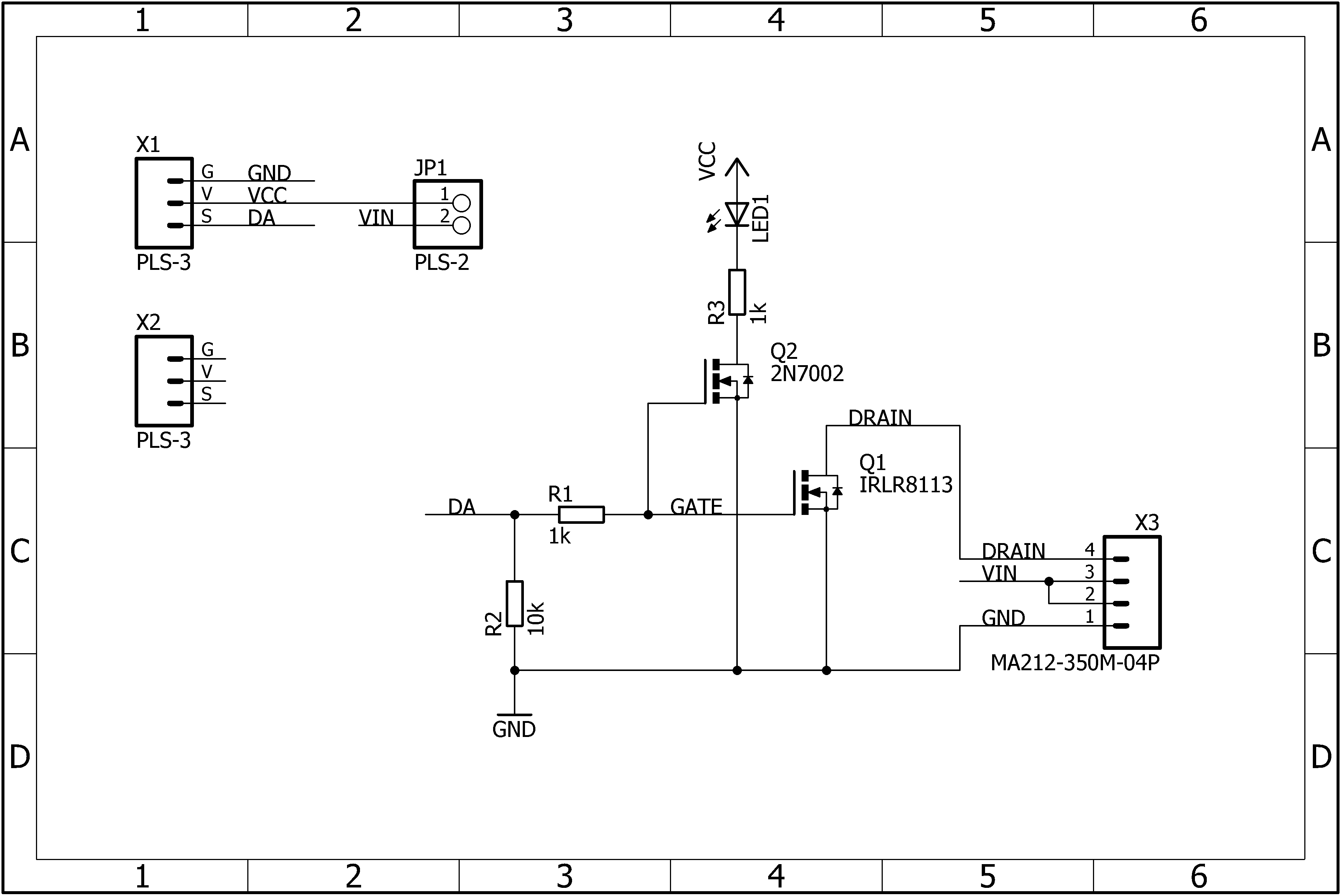
To control the Peltier I am planning to use the following scheme (attached)
Thank you for the reply.
If you have a spare minute, could you show me how to find this VGS turn on voltage. I looked at the diagrams that are in the data sheet but couldn’t find the relevant information.
I usually read a MOSFET datasheet by flipping to the first chart (graph) that's on page 3. That will show the VDS voltage versus current. There are several lines on that chart, one for each different VGS voltage.
If the 5V line is the highest or it's very close to the 10V line then you've got your hands on a "logic level" MOSFET. If 5V is near the bottom then it needs 10V gate drive to achieve full performance.
The turn-on voltage usually is named threshold voltage, Vth or the like. Take the max value, add the voltage required for the intended current, to get the minimum required gate voltage.
Right, Vth is the begin of the linear operating area. That's why you have to add the voltage required for the desired current, in order to turn the FET on.
An additional question (while I am digging into the datasheets).
I have found a 12V 6A power source. Now I have the opposite problem: how do I connect to Arduino board that only needs 7V at most. I can use a resistance potential divider, but is it a good idea? Also, most of my resistors are below 5Wt
What else is powered from the Arduino's 5V and 3.3V pins? If there is not something like an LCD with backlight then it is safe to power the Arduino from 12V.
DrDiettrich:
Right, Vth is the begin of the linear operating area. That's why you have to add the voltage required for the desired current, in order to turn the FET on.
With FETs you only ever want full ON or full OFF.
Strinda, there are FETs that need 10V to turn full ON and others, logic-level FETs that only need 3V to turn full ON. They are made for TTL like Arduino pins, you put a 220 ohm resistor between the Arduino pin and the FET gate to keep the Arduino pin safe.
The FET you chose does need at least 10V to open fully. It is not logic level. The NPN can feed the 10V to the FET gate.
Same company makes the IRLZ44N which is logic level. On eBay for 1 is maybe 80 cents but look more, I found 60 for $10 and 10 for $3.50 kind of deals. 60 for $10 is about 15 cents each and I had $10 to spend.
I have done a lot of work with power FETs over the years. I think you should always go for a gate voltage that will give full enhancement under any conditions ie for a logic level FET, usually 5V, for others 10V is usually the go. Trying to pick an intermediate voltage, sufficient for the current required, but less than the rated maximum could easily put you in the linear range ("burn out in 5 seconds") if you miscalculate, or if you have a "minimum" instead of a typical example FET.
In all electronic circuits it's good practice to have a safety margin of 10-20% above worst case. More is not a problem, but not always required.
For a MOSFET switch the ON voltage is given by the controller Vcc, and a FET is selected that supplies (at least) the required current for this gate voltage. If you select a FET with more current, the gate capacity may be higher and increase the time spent in the linear area and also burn out the FET. In detail with resistive or capacitive loads and PWM.
I bought logic level FETs because they're supposed to open for 3.3V to 5V gate operation.
Strinda, the FETs are all very weak to static electricity. More than 20V across the wrong leads will break the logic level FETs I have... yet I have not ruined any while using them.
Hi
DrDiettrch - totally agree with you on the gate capacity issue. Most of my power FET work over the years has been switch mode power supply design / development. The trick here is to pick a FET with a high enough current rating to do the job, but not too much over, as per your comments, the gate capacity being higher with larger FETS. Most of my time in selecting FETs for a particular task was doing the trade off between current rating, RDS on figure, and gate capacity / gate charge figure. Miller effect can also have big effect on rise-time. (Drain to gate capacity). The numbers can all change with voltage rating - the higher this is, the harder to get a good compromise on RDS on and gate charge / capacity, so voltage rating should not be higher than needed.
Once a suitable device is chosen, hit the gate as hard as you can to turn it on quickly, pass through the linear region as fast as possible and fully saturate when on. The RDS figure can vary significantly over the range of drive levels.
To turn on fully and fast you need current as well as voltage. A good driver for switch mode use would typically have 2 - 4 amps available.
Having said all that FETs have come a long way over the last 5 years or so. Very high current FETs (50amp class) now have gate capacities and charge figures that are very low compared to early offerings. Typical (non-isolated) switch mode efficiencies can be around 98% - 20 years ago when I first started working with these things around 90% was considered good.
Whatever is good for switch mode operation should also be good for PWM, but probably not quite as critical as frequencies are generally lower. At very high frequencies rise and fall times can become a significant part of the total cycle time, lowering efficiency.
Thank you all for the answers. I need some time to understand them, though:)
I have created a circuit: Peltier element + PC Cooler + MOSFET (while reading replies I decided to do two things 1) find an easier power switch solution read out of the box 2)try your solutions separately - to see how they work)
Some more help needed
I still have difficulty understanding if it is possibe to connect arduino to the same power source.
Also, if I don't solve the problem with the same power supply for the Arduino and Peltier and use two separate power supplies (the one above) + AAA power pack for Arduino - I wil have to connect the V- wires, right?
Hi
The thing I dont understand about your circuit is the "IRLR8113 +2N7002". I guess you are using the small FET (2N7002) to drive the large one (IRLR8113), but your schematic does not show how this is done and I can't see how it is possible. A darlington connection wont do the job, as your 5V gate drive is then shared between the 2 FETS and the drive to the IRLR8113 will probably be inadequate.
Show me how the 2 FETS are connected and I can make a better judgement.
Duck51:
Hi
The thing I dont understand about your circuit is the "IRLR8113 +2N7002". I guess you are using the small FET (2N7002) to drive the large one (IRLR8113), but your schematic does not show how this is done and I can't see how it is possible. A darlington connection wont do the job, as your 5V gate drive is then shared between the 2 FETS and the drive to the IRLR8113 will probably be inadequate.
Show me how the 2 FETS are connected and I can make a better judgement.
Regards
Rob
This is the component I have found in my local shop: HERE
As for the component's datasheet: HERE
Hi
Didn't realize that what you had was a manufactured module - not a couple of FETS connected together. The 2N7000 does nothing except drive the indicator LED. The IRLR8113 is driven direct by the Arduino output. The module already has a 1K ohm limiting resistor in the IRLR8113 gate lead, so there is no need for your external 1K resistor. Leave it out. Including it will slow the switching time down excessively. It is slow enough due to the internal resistor.
I did a simulation on the circuit and although switching is slow, it works OK in this application.
IRLR8113 dissipation is <500mW, (@ PWM of 10KHz) which is OK - it will get warm but not excessively hot.
Give it a go - it should work and it should not be possible to easily do any damage.
Note that the mosfets, being wired onto a board, have reasonable protection against static damage, so no special handling precautions are needed. Be careful however, not to drop scraps of wire, tools, splashes of solder etc onto a powered board - nothing protects against that sort of disaster.
If you are using a UNO or any of the others with a DC input socket, you should be able to use this to power the Arduino from your 12V supply. I am doing this on my current project where just about all the peripherals run on 12V. I have no separate supply for the Arduino.

