is there a place where you can see what pins are mapped to a port register on the pico?
im looking to read the entire bank of pin states at the same time and im not having much luck.
is there a place where you can see what pins are mapped to a port register on the pico?
im looking to read the entire bank of pin states at the same time and im not having much luck.
rp2040-datasheet.pdf (4.7 MB)
Go from page 257
ok 2 followup questions,
I'm not seeing a status register I'm at page 309(seen a mess of registers pertaining to interrupts,perhaps that's the same thin?), is their specific register I'm looking for?
and how do you read these registers in arduino?
page 5 shows the pin layout, but not where the named gpio are mapped internally
like:
DDRD - The Port D Data Direction Register - read/write
PORTD - The Port D Data Register - read/write
PIND - The Port D Input Pins Register - read only
I haven't used Mbed at all but after a quick survey of the docs it looks like there is a mapping of the Arduino pins to the Pico pins like:
D2 >> P1_11
etc.
i didnt think about the core being a factor but im on the earl philhower lib.
there is a micropython example of how to do this:
is that map from a file in the mbed core? if so what file?
as i delve more into this i am realizing that perhaps each pin is its own entity which would make port reading not a probability. each GPIO has its own register.
long attempt =GPIO0_STATUS;
Logicanalyzerproto:12:15: error: 'GPIO0_STATUS' was not declared in this scope
   12 | long attempt =GPIO0_STATUS;
      |               ^~~~~~~~~~~~
exit status 1
'GPIO0_STATUS' was not declared in this scope
This is not entirely true. Pico has its own GPIO structure and the concept of a port as in AVR does not apply to them. However, reading and writing many pins (at much as all) at the same time is quite possible.
The Pico doesn't support the idea of ports like on an Arduino. Each GPIO on the pico is a single i/o. In MicroPython you could group 8 together and treat them programmatically like a port but I think you will have to use an Arduino-like IDE to address them like you talk about in your first post.
void pollPins(int pins[16]) {
  bool val;
  double pinStat;
  double pinHold;
  for (int b = 0; b <= 15; b++) {
    val = digitalRead(pins[b]);   // read the input pin
    int pinHold = val << b;
    if(val){
      pinStat += pinHold;
    }else{
      pinStat -= pinHold;
    }
  }

}
what i have come up with pretty quickly .
do you happen to know where i could see an example, please?
Pay attention to the following functions of SDK++
// READING
static bool gpio_get (uint gpio)                     // read one pin
static uint32_t gpio_get_all (void)                  // read all pins at once

// WRITING
static void gpio_put (uint gpio, bool value)       // write one pin
static void gpio_put_all (uint32_t value)          // write all pins at once
static void gpio_set_mask (uint32_t mask)         // setting pins ( to HIGH) by bitmask
static void gpio_clr_mask (uint32_t mask)        // clear pins by bitmask
static void gpio_put_masked (uint32_t mask, uint32_t value)  // set the given value by mask
... and many others
See Pi Pico C++ SDK, chapter 4.1.10
Addition - all SDK function available in arduino using earlphilhower pico library
reading this i feel like i have been misleading somehow, and i am sorry for that , for clarity i am using arduino 1.8.19, and the earlphilhower pico library 2.3.2. the reference to micropython was just the example i found where they could read and write the registers correctly. I'm sorry if i created some confusion. ![]()
duh, i seen the declaration, makes sense the avrs have ports because they are 8 bit, 8 bits in a port, the pico is 32 bit, 32 bits in a port all the gpio would comparatively be a single 32 bit port for the most part, it can process them all at the same time.
welcome to my second monday ![]()
• gpio GPIO number
Returns
• Current state of the GPIO. 0 for low, non-zero for high
4.1.10.4.10. gpio_get_all
static uint32_t gpio_get_all (void)
Get raw value of all GPIOs.
Returns
• Bitmask of raw GPIO values, as bits 0-29
thanks b707!
Understood. No problem. Like I said, I'm not familiar with that library. If I want to create "ports", I might think about using the PIO.
Now that I've caught up reading the thread, I see from b707's post that the complete Pi Pico C++ SDK is available to Arduino through the earlphilhower library so you can do what ever you like.
The features mentioned in #10 do not complete the list.
The fastest and, without a doubt, the most interesting method of accessing pins on Pico is through the Pio state machine, as mentioned @EmilyJane
Using Pio sm, in one project I output 7 independent signals to 7 pins with a frequency of more than 20 MHz
for thanks use the Like button ![]()
i haven't got to state machines yet with the pico, but it would fit the application, so i may have to look into it, im working on a 16 channel logic analyzer with independent trigger that collects information and transmits it wirelessly. from what i have read about the pio they are pretty awesome, and i have used it through other libraries mainly bodmers tft_espi which uses pio for parallel displays . it seems to make a pretty remarkable difference.
Yes it does.
No it is not. There are two 32 bit registers which make up the ports.
No it is the replies that are misleading.
No that is not the way to do it. You are going through bit by bit assembling the registers you need. This is done by the bit reading of the two 32 bit port registers.
Please read the data sheet I posted in the first reply.
I am amazed that so many people here do not have a clue as to the structure of this processor.
ok in case anyone stumbles on this in the future, from what i have figured out by trial and error its not as straightforward as it seems.
first you have to set the pin mode, which for gpio is 5 or GPIO_FUNC_SIO, it works both ways that looks like this :
from:rp2040-datasheet.pdf pg29
for (int i = 0; i < 30; ++i) {
    gpio_set_function(i, GPIO_FUNC_SIO);
    if (i >= 26) {
      gpio_disable_pulls(i);
      gpio_set_input_enabled(i, false);
    }
  }
which i gleaned from here : https://github.com/raspberrypi/pico-examples/blob/master/adc/adc_console/adc_console.c
and given consideration for the below gotchas
void setAllDigital(int pins[], int pinCount) {
  for (int i = 0; i < 30; ++i) {
    if (i == 23 || i == 24  || i == 25  || i == 29) {
      break;
    } else {
      gpio_set_function(i, GPIO_FUNC_SIO);
    }
  }
}
then you have to set the port direction 0 for input 1 for output:
gpio_set_dir_out_masked(0b00000000111000000011111111111100);
which i a sure there are a million more elaborate ways to do this but i was putting together a manual human verifiable example .
then the original thing that brought me here would be :
gpio_put_all (0b00101010101010101010101010101010);
some gotchas > led is on gpio 25 so kinda pointless
the variable that holds the pins is MSB first.
23,24 and 29 arent broke out on the pico, (have no actual idea what they do at this point but will be looking into this . )
Blockquote
What are GPIO 23,24,25 and 29 used for on the Raspberry Pi Pico board?
These GPIOs are used on the Raspberry Pi Pico board for the following purposes:
• GPIO23 goes to the PS pin of the voltage regulator, to adjust it between PFM and PWM mode.
• GPIO24 is the centre of a 5.6kΩ/10kΩ voltage divider off the VBUS from USB, on the USB side of a diode, so it
detects if USB is supplying voltage
• GPIO 25 is the on-board LED
• GPIO29/ADC3 is another voltage divider to measure VSYS, but with an extra FET in place so the divider can’t leak
into the ADC and 3.3V rail, when the 3.3V rail is off
from: https://datasheets.raspberrypi.com/pico/raspberry-pi-pico-faq.pdf
page 6
and the first 3 bits are always zero because there is no gpio29,30,31
i did read the datasheet and was reading it from the bookmarker indicated , it just really didnt tell me how to interface with the registers, after looking at your information as well as the sdk information i am now learning my way through it.
any new technology is indistinguishable fro magic, until you learn the trick. and these are still fairly new at least to the hobby world, and especially to weekend warriors who dont have time to read understand and digest 647 page datasheets, or the others that i often encounter which dont care how it works just that it works and does what they want.
i really do appreciate everyone's input, thanks guys !
What are the names of these two 32 bit port registers from the RP2040 data sheet?
2.19.2. Function Select
CTRL & Status, is what i believe he is referring to . actually detailed on pg 265
the end of pg267 outlines the bits for GPIO0_STATUS and pg268 outlines GPIO0_CTRL, which are the registers that are interfaces with whenever a pin is manipulated.
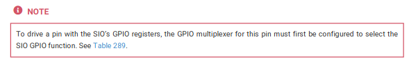
each gpio has these registers, but from what ive been poking about they are pretty useless if you don't set the gpio function first.
when the pico is first powered up the pins are all set to function 31, except for 31, and 30 which always pop up 17 and 18 .