Pi Pico SPI issues

HELP REQUEST !!

I’m not working on a real project, but evaluating the new processors.

I use different approaches to generate a sine wave (I2C, SPI, I2S. .. )

In this moment I'm using a 10-bit SPI DAC 5V
I use the same simple SW for testing the different processors.

I can share the following results I have got

Arduino uno Sine WAVE 101,6Hz

Teensy 4.1 Sine WAVE 2,57khZ

PI_PICO Sine WAVE 53,35 Hz (processor speed 125 MHZ)

Good news: I'm able to generate a sine wave with a SPI DAC and the Pi PICO

Bad news: The sine frequency is smaller than the one I got with Arduino Uno

My expectation was to generate a Sine with a frequency between the one with Arduino Uno and the Teensy 4.1 one.

What’s wrong in my thoughts with PI PICO ?
Any hint would be great appreciated!!!

SW used

/*
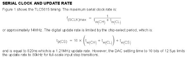
A demo of the TLC5615 10-bit SPI DAC with Arduino Uno
Generates a test sine wave, rising ramp wave, and
some custom voltage outputs for hardware testing.

Gadget Reboot

*/

#include <Wire.h>
#include <TLC5615.h>

// SPI chip select pin
#define dac_CS 17

// current position in waveform/sample playback
int sinePos = 0;

// create DAC object using chosen chip select pin
TLC5615 dac(dac_CS);

// sine wave data table generated with Sine Look Up Table Generator Calculator
const PROGMEM uint16_t sineTable[256] =
{
512, 524, 537, 549, 562, 574, 587, 599,
611, 624, 636, 648, 660, 672, 684, 696,
707, 719, 730, 741, 753, 764, 774, 785,
796, 806, 816, 826, 836, 846, 855, 864,
873, 882, 890, 899, 907, 915, 922, 930,
937, 944, 950, 957, 963, 968, 974, 979,
984, 989, 993, 997, 1001, 1004, 1008, 1011,
1013, 1015, 1017, 1019, 1021, 1022, 1022, 1023,
1023, 1023, 1022, 1022, 1021, 1019, 1017, 1015,
1013, 1011, 1008, 1004, 1001, 997, 993, 989,
984, 979, 974, 968, 963, 957, 950, 944,
937, 930, 922, 915, 907, 899, 890, 882,
873, 864, 855, 846, 836, 826, 816, 806,
796, 785, 774, 764, 753, 741, 730, 719,
707, 696, 684, 672, 660, 648, 636, 624,
611, 599, 587, 574, 562, 549, 537, 524,
512, 499, 486, 474, 461, 449, 436, 424,
412, 399, 387, 375, 363, 351, 339, 327,
316, 304, 293, 282, 270, 259, 249, 238,
227, 217, 207, 197, 187, 177, 168, 159,
150, 141, 133, 124, 116, 108, 101, 93,
86, 79, 73, 66, 60, 55, 49, 44,
39, 34, 30, 26, 22, 19, 15, 12,
10, 8, 6, 4, 2, 1, 1, 0,
0, 0, 1, 1, 2, 4, 6, 8,
10, 12, 15, 19, 22, 26, 30, 34,
39, 44, 49, 55, 60, 66, 73, 79,
86, 93, 101, 108, 116, 124, 133, 141,
150, 159, 168, 177, 187, 197, 207, 217,
227, 238, 249, 259, 270, 282, 293, 304,
316, 327, 339, 351, 363, 375, 387, 399,
412, 424, 436, 449, 461, 474, 486, 499
};

void setup() {

// initialize DAC
dac.begin();
}

void loop() {

    // sine wave
    dac.analogWrite(pgm_read_word(&(sineTable[sinePos])));
    sinePos++;
    if (sinePos >= 256)
      sinePos = 0;

}

HARDWARE USED FOR THE TEST

PI PICO & TLC5615 10-bit SPI DAC (level shifter is required)

  1. It is easy to understand that output signal frequency is limited by SPI communication speed (not processor frequency)
  2. Take a look on the library source code
void TLC5615::analogWrite(uint16_t value)
{
    // Prepare the buffer
    value = (value & 0x3ff) << 2;
    
    // Assert SPI bus
    digitalWrite(_ss, 0);
    
    // Perform SPI Transfer
    SPI.beginTransaction(SPISettings(20000000, MSBFIRST, SPI_MODE0));
    SPI.transfer16(value);
    SPI.endTransaction();
    
    // Deassert SPI bus
    digitalWrite(_ss, 1);
}

SPI clock is hardcoded as 20MHz
If MCU cannot set such speed for SPI it is trying to use some different values (and it is difficult to predict which one will be used).
I guess this explains your results.

It is the use of digital write to assert and de assert the chip select line that is killing the speed of your output.

It is easy enough to have a a direct port addressing or for a Pico a line of assembler to you this.

I have had no trouble getting higher frequencies especially when using a floating point pointer and increment value.

I recently published a Pico Voice effects generator in the MagPi magazine numbers 106 and 107 that shows you how to do it. Free PDF download for both issues.

In addition to what was mentioned above there are other factors which drops down SPI speed.
Each time you call analogwrite function you activate and deactivate SPI.
Also DAC IC is not so simple as it is possible to think (see attached image)

5615

Thanks a lot for your help!!
I will deep following your hint!

THANKS for your comment.
I have just down loaded both MagPi.
Great work !!
I lot of learning stuff, I will need some time to digest it

Best wishes.

Good. Just note that this was not programmed under the Arduino IDE as I wrote this before it was up and running. It uses the Raspberry Pi Pico system which is a lot harder to use than an Arduino.

Using the new PicoSPI library I have got frequency sine values according my expectations
Thanks for your comments
Still a lot to be learn

This is the new code valid only to Pi Pico
The previous on I shared runs in Arduino Uno, Teensy 4.1 and Pi Pico (in this last HW with poor result)

/*
A demo of the TLC5615 10-bit SPI DAC

Sine WAVE Arduino uno using SPI.h library

SPI_clock    20MHz       Sine Wave       101,6Hz

Sine WAVE Teensy 4.1 using SPI.h library

SPI_clock    20MHz       Sine Wave       2,57khZ 

Sine WAVE PI_PICO (133 MHz) using SPI.h library

                                         56,10 HZ   

Sine WAVE PI_PICO (133 MHz) using PicoSPI.h library

 SPI_clock     1MHz       Sine Wave  73,53 Hz
 SPI_clock    10MHz       Sine Wave  561,8 Hz
 SPI_clock    20MHz       Sine Wave  1,029 KHz

// used pins for SPI0
const uint8_t SPI_MISO = 16;
const uint8_t SPI_CS = 17;
const uint8_t SPI_SCK = 18;
const uint8_t SPI_MOSI = 19;

*/

#include <PicoSPI.h> // pico library

// GitHub - MarkTillotson/PicoSPI: Lightweight SPI library for RasPi Pico board using the RP2040
//
// PicoSPI library provides two objects for the RP2040 chip's two SPI units,
// PicoSPI0 and PicoSPI1.

// >>> It supports master mode only <<<

// The units are completely independent but each is limited to a particular subset of
// the Pico's pins, as shown on the various pinout diagrams. You would typically choose
// a contiguous set of 4 pins for a particular SPI unit, although this is not required.

// The configuration arguments are 4 pins, namely SCLK, MOSI, MISO and CS, in that order,
// and all must be supplied. Also a frequency, an SPI mode, and a flag "auto_transations".
// If auto_transations is true, every byte will automatically drive CS low for its transmission
// If auto_transations is false, you have to call beginTransaction() and endTransaction()
// explicitly to drive CS, but you can group multiple bytes within a "transaction".

// The PicoSPI library forces you to explicitly configure an SPI unit before you can
// use it - this is good as the existing different Arduino ports of the Pico are different
// about the default pins used! Explicit is always good for pin assignments(!)

// The clock frequency used is constrained automatically in the range 2500 - 25000000 (2.5kHz to 25MHz)
// as this is what the hardware can usefully support.

// current position in waveform/sample playback
int sinePos = 0;

// sine wave data table generated with Sine Look Up Table Generator Calculator
const PROGMEM uint16_t sineTable[256] =
{
512, 524, 537, 549, 562, 574, 587, 599,
611, 624, 636, 648, 660, 672, 684, 696,
707, 719, 730, 741, 753, 764, 774, 785,
796, 806, 816, 826, 836, 846, 855, 864,
873, 882, 890, 899, 907, 915, 922, 930,
937, 944, 950, 957, 963, 968, 974, 979,
984, 989, 993, 997, 1001, 1004, 1008, 1011,
1013, 1015, 1017, 1019, 1021, 1022, 1022, 1023,
1023, 1023, 1022, 1022, 1021, 1019, 1017, 1015,
1013, 1011, 1008, 1004, 1001, 997, 993, 989,
984, 979, 974, 968, 963, 957, 950, 944,
937, 930, 922, 915, 907, 899, 890, 882,
873, 864, 855, 846, 836, 826, 816, 806,
796, 785, 774, 764, 753, 741, 730, 719,
707, 696, 684, 672, 660, 648, 636, 624,
611, 599, 587, 574, 562, 549, 537, 524,
512, 499, 486, 474, 461, 449, 436, 424,
412, 399, 387, 375, 363, 351, 339, 327,
316, 304, 293, 282, 270, 259, 249, 238,
227, 217, 207, 197, 187, 177, 168, 159,
150, 141, 133, 124, 116, 108, 101, 93,
86, 79, 73, 66, 60, 55, 49, 44,
39, 34, 30, 26, 22, 19, 15, 12,
10, 8, 6, 4, 2, 1, 1, 0,
0, 0, 1, 1, 2, 4, 6, 8,
10, 12, 15, 19, 22, 26, 30, 34,
39, 44, 49, 55, 60, 66, 73, 79,
86, 93, 101, 108, 116, 124, 133, 141,
150, 159, 168, 177, 187, 197, 207, 217,
227, 238, 249, 259, 270, 282, 293, 304,
316, 327, 339, 351, 363, 375, 387, 399,
412, 424, 436, 449, 461, 474, 486, 499
};

void setup() {

// configure SPI0 for

// SCLK = pin 18 (alternative pins are 6, 18, 22)
// MOSI = pin 19 (alternative pins are 7, 19)
// MISO = pin 16 (alternative pins are 0, 16, 20)
// CS = pin 17 (alternative pins are 1, 17, 21)
// and for 1MHz clock, in mode 0, without automatic transactions
if (! PicoSPI0.configure (18, 19, 16, 17, 1000000, 0, false))
{
while (true) {}
}

/*

  • 1000000 clock 1MHz Sine Wave 73,53 Hz
  • 10000000 clock 10MHz Sine Wave 561,8 Hz
  • 20000000 clock 20MHz Sine Wave 1,029 KHz

*/

}

void loop() {

uint16_t value;
byte value_low;
byte value_high;

    // sine wave

        // Prepare the buffer
         value =  pgm_read_word(&(sineTable[sinePos]));
         value = (value & 0x3ff) << 2;

        
        value_low =lowByte(value);
        value_high = highByte(value);


        PicoSPI0.beginTransaction() ;
        
          PicoSPI0.transfer (value_high) ;   // PicoSPI  library only byte transfer are implemented
          PicoSPI0.transfer (value_low) ;   
        PicoSPI0.endTransaction() ;


    sinePos++;
    if (sinePos >= 256)
      sinePos = 0;

}

This topic was automatically closed 120 days after the last reply. New replies are no longer allowed.