PID controller and Tuning

I think the code you posted cannot work correctly, partly because of the serious error I've already pointed out.

Since you have told us nothing about the actual steering arrangement, the only test I can suggest for correctness is to hold the model in various orientations and check if the mechanical arrangement takes the appropriate action to correct for known errors, small and large.

Change the PID from DIRECT to REVERSE.

1 Like

Thank you guys all the help!

We had nice weather yesterday, so I had the chance to test the now PID-controlled steering wheel.
The first attempts were disappointing. The values I used were about the same:
P=1 ; I=1 ; D=1
P=2 ; I=1 ; D=1
P=2 ; I=0.5 ; D=1
P=2 ; I=0.5 ; D=0.5
...
etc...

Unfortunately, the boat was unable to go straight. The boat was in a huge zigzag, there was not a second when it was going straight. The P value didn't seem to change the behaviour of the rudder, but if I remember correctly, with a high D value the rudder started to jerk like crazy. I had given up completely, but tried one last random value:

P=1.2 I=0.2 D=0.2

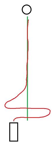
And it was almost a perfectly working control. The movement of the boat looked like this:

At the start there is a huge overshoot in both directions. Even when the boat is almost perfectly on course. If I can fix this, the control would be perfect.

But I don't know what's causing these two overshoots:

  • It requires fine tuning of P, I, D
  • Wind-up occurs and this should be handled. However, it is interesting that this is not the case in the later stages.

Question 2:

Otherwise, should the PID controller be reset?
After all, I use it without autopilot on by default, I just control the rudder with a pot. If I press a button it switches to autopilot mode, and then the PIDcompute() lines are only executed. However, if I turn off autopilot, then run it manually for 1 hour, then turn autopilot back on, shouldn't that cause a problem with the compute? Or would it be more appropriate that when I start the autopilot mode I turn on the PID control and turn it off as soon as I exit it?

It seems you chose too large values for P and/or I and/or D. That results in an overshoot.
Also you might need a smoothing filter before sending your measurements to the PID. The D action may cause instability if there is noise on the sensor values. You can also set D to 0 to eliminate this problem. Nothing wrong with a PI controller if it makes you reach your goal...
Best would be to record values of error, p, i and d along the track. That would give you insight on the main contributor to the signal sent to the actuator.

You may want something different for startup. I expect you're getting integral windup when you switch to auto and the PID tries to get you on course. Perhaps use a second PID to get your cross track error down initially and then use your original to stay on course.

The problem is that if I go in the right direction and turn on the pilot, the oscillation still happens.

Is there a formula to eliminate the windup that I could easily implement? Or maybe it would help to set the P value to 0.4 instead of 1.2 after engaging the autopilot, and then let the full 1.2 value on after a few seconds? Or does this completely fool the PID controller?

Is it possible that if I start with a low P value and after 2 seconds I switch to a higher P value, the overshoot will be higher than if I had started with a higher P value?

Because in this case the deviation stays for a longer time, so when I get a chance to correct more by increasing P, the output will shoot out more because of the I value.

Is this correct or completely wrong?

Unfortunately, the problem is that I am not familiar with basic things about PID control. There are many tutorials in English, but my English is not good.

The main problem I don't understand is that time matters in I control. It corrects based on the elapsed time. But how is the time calculated, when does the PID control function sample? Only when I call the PIDCompute() function? AND does the time between the two calls count?

Somewhere in your pid library you set the sampling rate...
And somehow this sampling should be done in your code. Either by a timed interrupt or by a fast loop with a call to update the pid.
So it is about time you share your code...
If your boat is out of the water and pointing in the right direction, what does the rudder do? Is it straight?
By the way, time also matters in D control...

I continue to suffer with PID control.

After starting the autopilot, I noticed that my boat hardly turns left at all. If the target is to the right, it turns over it, then only very slowly, after a very long time, turns back to the left, and only then reaches the target heading.

So there is a problem with the left side.

The servo that moves the rudder is not installed perfectly, so although the centre point is at the 1500 PWM value, it reaches the final rudder position to the left sooner, so I had to lower the limit.

int rudderleft=1300;
int rudderright=1900;
int ruddercenter=1500;

So, with a centre position of 1500, you only need to move 200 to the left of the centre position, and 400 to the right, to turn left and right at the same angle.

Outputtemp=map(Output,-180,180,rudderleft,rudderright);

But here the value returned from the PID is evenly split between 1300 and 1900, so I assume that if I should go straight it will be 1600, and if I should turn a few degrees to port it will still read almost 1600, which would still turn the boat to starboard?

The interesting thing is that sometimes it works perfectly.

#include <NMEAGPS.h>
#include <GPSport.h>
#include <PID_v1.h>
#include <Servo.h>

const byte RudderServoPin = 10;
Servo RudderServo;

int rudderleft=1300;
int rudderright=1900;
int ruddercenter=1500;

static NMEAGPS gps;
static gps_fix fix;

double Setpoint, Input, Output;
double OutputTemp;                                                  

double Kp = 1.0, Ki = 0.0, Kd = 0.4;
PID myPID(&Input, &Output, &Setpoint, Kp, Ki, Kd, DIRECT);

const float targetlan = 42.683336;
const float targetlon = 12.082045;
const NeoGPS::Location_t base(targetlan, targetlon);

void setup() {
  
  RudderServo.attach(RudderServoPin);

  gpsPort.begin(38400);

  Setpoint = 0;                                               // Desired bearing is 0° off bearing to base
  myPID.SetOutputLimits(-180, 180);
  myPID.SetMode(AUTOMATIC);
}

void loop() {
  servocontrol();
}

void servocontrol() {
  int bearing = fix.location.BearingToDegrees(base);
  int headingDegrees = fix.heading();

  // Calculate a heading error in the range -180 to +180 and reverse the heading
  Input = ((bearing - headingDegrees + 540) % 360) - 180;
  
  myPID.Compute();
  
  Outputtemp=map(Output,-180,180,rudderleft,rudderright);    
  
  RudderServo.writeMicroseconds(Outputtemp);
}
Real boats have asymmetries too. The rotation of a propeller and the interaction of the spinning water with the hull above the propeller can induce nonlinear behavior.

Like the first term in a Taylor series, PID can work pretty well controlling the error from a setpoint as a first order linear system. If the nonlinearities in the sensor or control are significant, you can transform them before or after the PID controller. PID is assuming linearity, but you can transform nonlinear terms to linear.

It is unclear what you are asking, but maybe something like this would transform the control output to have two different slopes:

  Outputtemp=(Output < 0 ?
               map(Output,-180,0,rudderleft,ruddercenter) 
             : map(Output,0,180,ruddercenter,rudderright)) ;

(Edited days later to replace zeros in the RHS with ruddercenter. My zeros were horribly wrong. See far below in the thread. )

Very poor choice of starting PID K values.

You should start with Ki and Kd set to zero, and determine a reasonable P term first (which may change in later stages of process).

There are many tutorials on line for systematic approaches to "PID tuning", which phrase you can use to search for them.

Why do you write to your servo with .writeMicroseconds()?
What strange scale is that?
I think you want to put your servo in a certain position (angle). I have no clue how to express an angle in micro seconds (or it must be degrees minutes seconds micro seconds, but then 1000 microseconds is far far less than 1 degree...)
What is the time base of this library (and of ki and kd?)? Are you supposed to call it at regular intervals?
How long does the gps.fix take to return? Does it have a fix before the boat starts (the first fix may take more time than the next).
Integral windup can be eliminated by setting ki=0.
Noise problems can be eliminated by setting kd=0.
So do as @jremington suggested and start with proportional control. Take boat out of the water and program a goal 100 km north. Point your boat in northern direction. Now the rudder should be straight. If not, adjust length of servo to ruther connection or mapping... once that is done, put boat in western direction. Now rudder should be in the utter corner... and so on...

Just a scale factor and offset. By convention 1500 usec = neutral servo arm position, 1000 and 2000 usec are +/- 90 degrees, but the details vary between servos and manufacturers.

Of course...
...how did they get to usec????
I mean, I can accept an elbow, an inch, a foot, a Tesla, but usec???
...anyway, thanks for your explanation!

In the "old days" (about 40 years ago when digital servos became popular) it was milliseconds: 1.5 ms was considered neutral.

The servo control code is just a positive pulse in that range of widths, repeated 20 to 50 times per second. Easy to generate and easy to transmit for radio-controlled planes, boats and land vehicles.

I understand that a range of 1000 to 2000 is a nice range to map a servo angle. It fits in a 16 bit int, it is sufficient accurate (more accurate than hobby servos), but usec is just really making no sense...
Anyway, let us put this to a rest (the topic of this thread was PID control).

Wouldn't it make sense to scale the input to 1000-2000 as well?
Or maybe 0-4000 as the boat can also be in opposite direction...
Now kp has a unit usec per degree.... then it would be dimensionless...

More precise control. The two main choices are Servo::write() which takes values from 0 to 180 and Servo::writeMicroseconds() which takes a range from about 1000 to about 2000. Since the output range of a PID is arbitrary, the larger range gives more precise control. Internally to Servo, the 0-180 numbers get translated to the 1000-2000 range.

No, since the output range has nothing to do with the input range. Setpoint and Input must be in the same units. Output is entirely arbitrary and can be any convenient range.

You can use 0-180 for Output if it makes you more comfortable, but you will have less precise control.

Of course, I started with P control only, with I and D set to 0. I managed to set the value so that the oscillation stabilized. It never went to zero, but it never started to increase. The boat was snaking on the water. Then I started playing with the I and D values.

I use PWM values of 1000-2000 just out of habit. Of course, you could use 0-180, but it doesn't really matter.

I left the "I" tag out completely, unfortunately it really messes up the control of the boat, so I left the PD control. It worked perfectly fine that way... apparently. Because I noticed that the boat didn't seem to want to turn very much to the left. But I can see now that this could have been due to a faulty mapping. The asymmetric limitation of the servo caused the center to slip, so that in fact if it was supposed to turn a little to the left it would still turn a little to the right... Only at larger left deflections did the servo fall into actual left turns. I hope this solves the problem.

Outputtemp=(Output < 0 ?
               map(Output,-180,0,rudderleft,0) 
             : map(Output,0,180,0,rudderright)) ;

ANOTHER QUESTION: Unfortunately I am not fully familiar with the theory of PID control. There is a lot of literature, but it is all in English, and I don't know much English.

I can roughly imagine that we are 90 degrees to the left of the target. We pass -90 as input to the control, and then it returns with the outputs which write a servo value of say 0 to the servo, which is a full turn to the right.
Then at the next measurement we are only 35 degrees to the left, we pass -35 as input, then since we are using a D tag he sees the difference from the Setpoint is decreasing rapidly, so he only writes ~80 to the servo which is almost midpoint.
The next measurement we are only 5 degrees left of the target but he writes 110 to the output, which is already left steering (countersteering, since 90 is the midpoint, above that it is left steering)

So I understand that the output does not change in direct proportion to the input? The output can change much faster than the input?

I did not say it is needed. I proposed it might be handy to have the same scale on input and output side. And I guess that 'handy' is a personal thing here.

And if input and output are both on a 1000-2000 scale, you might use a PID controller with integer math. That would be faster. But with a boat that does not really matter.

With a p controller, the output is proportional to the error.
If you add the d action, it takes into account that the error is already decreasing, so it will decrease steering (it will anticipate).
If you choose kd too high, you get instability (it starts counter steering).
But, again, to me it is not clear what is the unit of time in your pid controller? And what takes care that it gets regular samples? And is your fix sufficiently fast to provide samples? Especially when starting? My phone sometimes takes a minute to get a fix. A boat may do a full circle in that time. And if you have an i action it will be all over the place.
I guess you will need some i action in the end to correct side wind, river flow or tidal currents.