PID controller and Tuning

Hi Guys!

I am building an autopilot for a boat.
The autopilot itself is already working, but there are problems with the heading:

The cube is the boat, the red circle is the destination and the green line is the perfect route. However, the boat is zigzagging along the red line. Clearly it is always oversteering, so a PID control would be needed.

I plan to use the following library:

I know the following values:

  • How many degrees of deviation between the current heading and the target.
  • The direction of the deviation. So I know whether to correct 20 degrees to the right or 20 degrees to the left.

Obviously I should aim for the deviation to be 0 degrees. For 0 degrees I set the yaw servo to 90 degrees, this corresponds to the centre position. For example, if there is a 20 degree deviation to the right, I write out about 110 values on the servo, so its gently turn the ship to right.

How should I put the PID parameters together?
Which value is INPUT, which value is OUTPUT
What is Setpoint and Direct?

Am I right in thinking that this is how it works?:

  • OUTPUT is the deviation from 0 degrees ?
  • And INPUT is the value that is written to the servo?

You need to google the principles of PID , it’s more about the boats response to a change in direction and what you are using to detect what the error from the destination.

The PID terms you get from experimentation - google tuning a PID loop

You should post your code which you are using and it's schematic

Backwards with respect to the black box which is a PID controller.

The input is the error, the output is information to the controlled system that would tend to correct the error.

a7

I guess you have a P controller now.
And P is too large.
Divide by 2 and see what happens.

PID will not make things easier or better unless you have the correct combination of kp, ki and kd...

For PID steering, it is convenient to use (heading - bearing} as the error term, and zero as the setpoint. That way the sign of the error immediately tells you right or left, for example.

To get rid of the zig zag, you need two error terms, the heading error and the cross track error.

Cross-track-control-strategy-The-cross-track-controller-computes-a-desired-heading-for

3 Likes

INPUT and SETPOINT are in the same units. INPUT is the current measurement and SETPOINT is the desired measurement. I would use your deviation for INPUT and the desired value is zero, so SETPOINT = 0.

OUTPUT is unitless. By default, it is a value from 0 to 255 but can change the limits. For a servo, I would use 0 to 180 (degrees) or 1000 to 2000 (microseconds).

The "Direct" means "increasing OUTPUT will tend to make the INPUT (deviation) HIGHER". Reverse means INPUT goes down as OUTPUT goes up. It depends on how the servo controls the rudder.

Ok, this is my simplyfied source code:

#include <NMEAGPS.h>
#include <GPSport.h>

static NMEAGPS  gps;
static gps_fix fix;

int headdirection = 0;

float targetlan = 42.683336;
float targetlon = 12.082045;


void setup() {
  pinMode(10, OUTPUT);
  gpsPort.begin( 38400 );
}


void loop() {
  servocontrol();
}


void servocontrol() {

  NeoGPS::Location_t base( targetlan, targetlon );

  int bearing = fix.location.BearingToDegrees( base );
  int headingDegrees = fix.heading();

  int headingway = ((bearing - headingDegrees + 360) % 360);
  
  if (headingway > 180) {headdirection = 2;} else {headdirection = 1;}

  if (headdirection == 2) {
    int difference = 360 - headingway;
    
    if (differenc>40) {digitalWrite(10, 1200;} else {digitalWrite(10, (1500 - difference));}
  }
  if (headdirection == 1) {
    int difference = headingway;
    if (differenc>40) {digitalWrite(10, 1800;} else {digitalWrite(10, (1500 + difference));}
  }
}

So, the main function is the servocontrol().
First i set target GPS coordinates:

NeoGPS::Location_t base( targetlan, targetlon );

Then make some calculation to get the right course from current position to target position:

int bearing = fix.location.BearingToDegrees( base );
  int headingDegrees = fix.heading();

After that, i want to know where to i need to rotate servo, i do this:

  int headingway = ((bearing - headingDegrees + 360) % 360);
    if (headingway > 180) {headdirection = 2;} else {headdirection = 1;}

If headdirection=2 then i need to rotate the servo to the right, else i need to rotate to left.
From this point i seperate the two rotating way situation, but in every situation i do the same:

int difference = 360 - headingway;

OR 

int difference = headingway;

With this lines i get the "error" from the 0°...
Then i do this:

if (differenc>40) {digitalWrite(10, 1200;} else {digitalWrite(10, (1500 - difference));}

So, there is two case in every situation. First case: if the error greater than 40°, then i made a big servo steer, no matter how great the error is. But after the error reduced bellow 40° i only made a little servo steer, reference to the error size.

It works, the steering working, but doing this:

So, i need to set PID control.

Of course i know, that manually i can made better resoults by increase 40°, or mapping the values, but it is manual. I think PID controller can made for me it automaticly...

Maybe it will be working?:
Becouse the wrong weather i cant try outdoor :frowning:

#include <NMEAGPS.h>
#include <GPSport.h>
#include <PID_v1.h>

static NMEAGPS  gps;
static gps_fix fix;

double Setpoint, Input, Output;
double Kp=1, Ki=1, Kd=1;
PID myPID(&Input, &Output, &Setpoint, Kp, Ki, Kd, DIRECT);

int headdirection = 0;

float targetlan = 42.683336;
float targetlon = 12.082045;


void setup() {
  pinMode(10, OUTPUT);
  gpsPort.begin( 38400 );

  Setpoint = 0;
  myPID.SetMode(AUTOMATIC);
}


void loop() {
  servocontrol();
}


void servocontrol() {

  NeoGPS::Location_t base( targetlan, targetlon );

  int bearing = fix.location.BearingToDegrees( base );
  int headingDegrees = fix.heading();

  int headingway = ((bearing - headingDegrees + 360) % 360);
  
  if (headingway > 180) {headdirection = 2;} else {headdirection = 1;}


  if (headdirection == 2) {
    int difference = 360 - headingway;
    Input = difference;
    myPID.Compute();
    Output=map(Output, 0,180,0,500)
    digitalWrite(10, 1500+Output } 
  }
  
  if (headdirection == 1) {
    int difference = headingway;
    Input = difference;
    myPID.Compute();
    Output=map(Output, 0,180,0,500)
    digitalWrite(10, 1500-Output }
  }
}

So i feed the PID with differenc from setpoint, then compute OUTPUT

Input = difference;
myPID.Compute();

After that i get OUTPUT value from 0 to 180. I map it to fill 1000-1500 or 1500-2000 servo range
Then i write it to servo

    Output=map(Output, 0,180,0,500)
    digitalWrite(10, 1500+Output }

More like:

#include <NMEAGPS.h>
#include <GPSport.h>
#include <PID_v1.h>
#include <Servo.h>

const byte RudderServoPin = 10;
Servo RudderServo;

static NMEAGPS gps;
static gps_fix fix;

double Setpoint, Input, Output;

// Read up on PID Tuning to learn how to set these
double Kp = 1.0, Ki = 0.0, Kd = 0.0;
PID myPID(&Input, &Output, &Setpoint, Kp, Ki, Kd, DIRECT);

const float targetlan = 42.683336;
const float targetlon = 12.082045;
const NeoGPS::Location_t base(targetlan, targetlon);

void setup() {
  RudderServo.attach(RudderServoPin);

  gpsPort.begin(38400);

  Setpoint = 0;                           // Desired bearing is 0° off bearing to base
  myPID.SetOutputLimits(1000.0, 2000.0);  // servo.writeMicroseconds() control
  myPID.SetMode(AUTOMATIC);
}

void loop() {
  servocontrol();
}

void servocontrol() {
  int bearing = fix.location.BearingToDegrees(base);
  int headingDegrees = fix.heading();

  // Calculate a heading error in the range -180 to +180.
  Input = ((bearing - headingDegrees + 360) % 360) - 180;
  myPID.Compute();
  RudderServo.writeMicroseconds(Output);
}
1 Like

Wow ! you are Great!

Thank you for extend my code, it realy help!

So, am i right, that with this line?:

int headingway = ((bearing - headingDegrees + 360) % 360)-180;

I will get values -180 to + 180, and from this i will get write values 1000 to 2000 to servo?
That sounds very good. However, is there a way to make it so that if the deviation is greater than -90 and 90 then a fixed value is output to the servo (large turn), and if the error is below -90 and 90 then only the PID should count, like this?:

  Input = ((bearing - headingDegrees + 360) % 360) - 180;
  if ((Input<-90) || (Input>90)) {
         if (headdirection == 2) {RudderServo.writeMicroseconds(2000);} 
              else  {RudderServo.writeMicroseconds(1000);} 
  } else { myPID.Compute(); RudderServo.writeMicroseconds(Output);}

Or will the PID controller measure incorrectly with this solution?

There is, but it should not be necessary. The PID is fully capable of giving large outputs if the Input is large. Before you complicate your code, try with just the PID. After you tune the PID, if it doesn't turn hard enough you can add complications.

If you set 'Kp' to 5.55 your Output will saturate (=1000 or =2000) for any Input below -90 or above 90. That's because the error (Input - Setpoint) is multiplied by the Proportional term.

Thanks again!!

I did as you write, but i got problem with the Input values.
The positive side works great, values are 0 to 180.... But the negative side overflow... Reach like 65345, or so value... :frowning:

EDIT: oh, and one more question? Should i reset the values computed by PID when i turn off autopilot? or it is enoguh that i didnt call the myPID.Compute(); when i am out from autopilot?

Sounds like you are saving a signed value into an unsigned variable. Show your sketch if you want help sorting that out.

I am using your code. Just added a debug output, to watch it with Serial monitor.
Thera a lot of additional lines in my source code, but they dont affect this things....

Changes Marked with "<-----"

#include <NMEAGPS.h>
#include <GPSport.h>
#include <PID_v1.h>
#include <Servo.h>

const byte RudderServoPin = 10;
Servo RudderServo;

static NMEAGPS gps;
static gps_fix fix;

double Setpoint, Input, Output;
double OutputTemp;           <-------------------------------------------------------------                                        
// Read up on PID Tuning to learn how to set these
double Kp = 1.0, Ki = 0.0, Kd = 0.0;
PID myPID(&Input, &Output, &Setpoint, Kp, Ki, Kd, DIRECT);

const float targetlan = 42.683336;
const float targetlon = 12.082045;
const NeoGPS::Location_t base(targetlan, targetlon);

void setup() {
  Serial.begin(9600);
  RudderServo.attach(RudderServoPin);

  gpsPort.begin(38400);

  Setpoint = 0;                           // Desired bearing is 0° off bearing to base
  myPID.SetOutputLimits(1000.0, 2000.0);  // servo.writeMicroseconds() control
  myPID.SetMode(AUTOMATIC);
}

void loop() {
  servocontrol();
}

void servocontrol() {
  int bearing = fix.location.BearingToDegrees(base);
  int headingDegrees = fix.heading();

  // Calculate a heading error in the range -180 to +180.
  Input = ((bearing - headingDegrees + 360) % 360) - 180;
  myPID.Compute();
  Outputtemp=map(Output,-180,180,1000,2000);    <---------------------------------------------------------
  Serial.println(Outputtemp);                                        <---------------------------------------------------------
  RudderServo.writeMicroseconds(Output);
}

And with this, i get values in serial monitor from 1500 to 2000. If i arrived from the other side, then the values always 1500

I don't think this is correct:

  Input = ((bearing - headingDegrees + 360) % 360) - 180;

Instead, try

  Input = ((bearing - headingDegrees + 540) % 360) - 180;

It is always a good idea to put in print statements, so that you can verify that input, intermediate and output values make sense under various test conditions.

1 Like

I think, the values are good.
By the way its working now! Just added negative output limit :smiley:

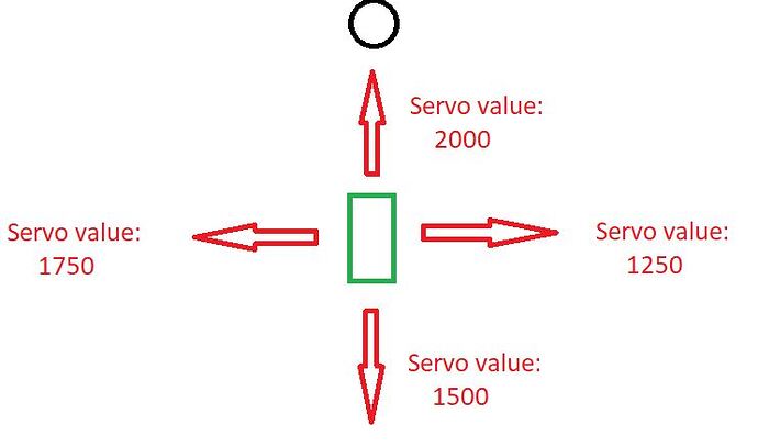
But there is another problem: Now the boat will go straight as an arrow with a servo value of 1500 when it is exactly straight away from the target, and it wants to turn the most (with values of 1000 and 2000) when I am heading straight for the target. So I have to change the direction exactly :smiley:

How do you think I can do this the easiest?

Adding lines after compute work like a charm, but not elegant. Any Idea? :smiley:

if (outputtemp>1500) {output=outputtemp-1500; outputtemp=2000-output;}
if (outputtemp<1500) {output=1500-outputtemp; outputtemp=1000+output;}

Did you make the change I suggested? If you did, then the sign of the error term is wrong. Just swap the heading and bearing terms.

Always post ALL your revised code, so we don't have to go back and forth so many times.

Tomorrow I will try what you wrote. Unfortunately it is very late here.

However, in the meantime I have a question: do I even do PID control now, or am I fooling myself?

So far, what I've basically done is to take the input value and map it to 1000-2000, which is the value I need for PWM. Practically no difference.

Or is it just because my PID control values are P=1, I=0, D=0? If I change these will I see a difference in the control behaviour? :smiley: