I have a dual shaft motor with a slotted disc attached on one of the shafts. It has a pulse counter placed underneath which measures how fast the disc is (and therefore the motor) is rotating. I am implementing speed control with a PID for continuously varying setpoints since this motor (along with 3 others) is to be employed in a 4 wheel robot car. The problem is that the output from the PID keeps oscillating and does not become stable. For example, if the setpoint is 211 rpm, then it will keep oscillating between 209 rpm and 213 rpm when I would prefer a stable output even if it is not at the setpoint (i.e 209 or 213 is fine as long as it remains there). One of my key questions is how do i get the output to stabilize instead of fluctuating? Because until the error and integral sum is 0, the output will keep changing.
I have attached my code below.
#define in1 8
#define in2 9
#define enc 18

int timer_load = 0;
int timer_match = 15624;

float count_per_sec, count;

float lastErr, errSum, timePrev;
float output, input, setpoint, prevOutput;
float kp, ki, kd;
int SampleTime = 1000; // 1 second

double outMax, outMin;

void initPID();
void modifySampleTime(int time); // time is in milliseconds
void setLimits(int min, int max);
void setPID(float kp, float ki, float kd);
void calcPID();
void setMotorSpeed(int speed);

void setup() {

 Serial.begin(9600);

 pinMode(in1, OUTPUT);
 pinMode(in2, OUTPUT);
 pinMode(enc, INPUT);

 // Create a timer for 60hz
 noInterrupts();
 // Reset the registers
 TCCR1A = 0;
 TCCR1B = 0;
 // Set prescaler to 1024
 TCCR1B |= B00000101;
 // Set the load and match value
 TCNT1 = timer_load;
 OCR1A = timer_match;
 // Enable compare match
 TIMSK1 |= (1 << OCIE1A);
 // Reenable interrupts
 interrupts();
r
 attachInterrupt(digitalPinToInterrupt(enc), motor_enc, RISING);

 initPID();
 setLimits(-255, 255);
 // set the setpoint for the pid loop
 setpoint = 211; // speed in rpm the motor should reach
 setPID(0.1, 0, 0);
}

void loop() {

 setMotorSpeed(output);
 // calculate input for the PID loop in rpm
 float rpm = (count_per_sec / 20.0f) * 60.0f;
 input = rpm;
 calcPID();
 Serial.print(setpoint);
 Serial.print(" ");
 Serial.print(rpm);
 Serial.println();
}

void initPID() {
 errSum = 0;
 lastErr = 0;
 timePrev = 0;
 output = 0;
 input = 0;
 setpoint = 0;
 kp = ki = kd = 0;
}

void calcPID() {

 unsigned long timeNow = millis();
 float timeDiff = (float)(timeNow - timePrev);

 if(timeDiff >= SampleTime) {

   float error = setpoint - input;
   float dInput = (float) (error - lastErr) / timeDiff;
   errSum += (ki * error);

   if (errSum > outMax) errSum = outMax;
   else if (errSum < outMin) errSum = outMin;

   output = (kp * error) + (errSum) + (kd * dInput);
   output += prevOutput;

   if (output > outMax) output = outMax;
   else if (output < outMin) output = outMin;

   // make changes for next run
   lastErr = error;
   prevOutput = output;
   timePrev = timeNow;

 }
}

void setPID(float kp_, float ki_, float kd_) {
 float SampleTimeInSec = SampleTime / 1000;
 kp = kp_;
 ki = ki_ * SampleTimeInSec;
 kd = kd_ / SampleTimeInSec;
}

void modifySampleTime(int time) {
 // time in milliseconds
 if (time > 0){
   float ratio = time / SampleTime;
   ki *= ratio;
   kd /= ratio;
   SampleTime = (unsigned long)time;
 }
}

void setLimits(int min, int max) {

 if (min > max) return;

 outMax = max;
 outMin = min;

 if (output > outMax) output = outMax;
 else if (output < outMin) output = outMin;

 if (errSum > outMax) errSum = outMax;
 else if (errSum < outMin) errSum = outMin;
}

void motor_enc() {
 count++;
}

void setMotorSpeed(int speed)
{
 /*
   Function sets motor speed.
   m is the motor name
 */

 // reverse rotation is speed is negative
 unsigned char reverse = 0;

 if (speed < 0) {
   speed = -speed;
   reverse = 1;
 }
 // cap speed
 if (speed > 255) {
   speed = 255;
 }

 // Send command to motors
 if (reverse) {
   // Setting speed of motor using L298N is only possible with PWM pins
   analogWrite(in1, speed);
   analogWrite(in2, 0);

 }
 else{
   analogWrite(in1, 0);
   analogWrite(in2, speed);
 }
}

ISR(TIMER1_COMPA_vect) {
 // noInterrupts();
 TCNT1 = timer_load;
 count_per_sec = count;
 count = 0;
 // interrupts();
}
That is typical behavior of an improperly tuned PID controller. Use the search phrase "PID tuning" to find tutorials on how to systematically go about choosing reasonable values for Kp, Ki and Kd. It will take some experimentation.
Under what conditions will the PID be stable? As long as the ouput is not equal to the setpoint, there will always be an error. And that error will only be 0 when output = setpoint, but there will also be an integral term that has to become 0 in order for the PID equation to output 0. I am fine with the PID output stabilizing slightly above or below the setpoint but that would be impossible because of the P and I terms.
You have an incomplete understanding of how PID works. That is easily corrected with reading and actual experience in tuning a properly designed controller.
Keep in mind that there is substantial measurement noise (so the proportional error term is almost never exactly zero, with random excursions above and below the average) and that PWM motor control is nonlinear.
PID can be applied in at least 2 ways regarding motors, one is to maintain position, the other speed.
presumably you understand how the derivative term can counter the proportional term to reduce a correction as the error approaches zero, minimizing overshoot.
but when maintaining a speed, the error cannot typically be zero, because some non-zero driving force is needed to maintain the speed of the motor (i.e. the motor voltage). Both the proportional and derivative PID output should be zero when a motor is at a target speed.
this is where the integral term is used to maintain some non-zero relatively stable value that can maintain the speed of the motor when the error is zero.
the integral output is the accumulation of a small fraction of the error and as it slowly grow, the correction due to P and D become less significant
And what are the resolution/accuracy of your speed measurement input, and the resolution/accuracy of your speed control output? Both are finite, and must to very precise to maintain target speed to a high precision. A low resolution encoder and/or a low-resolution or low frequency PWM output will likely be unable to maintain such precise control of motor speed.
Controlling RPM to within +/-2 RPM sounds pretty darned good to me!
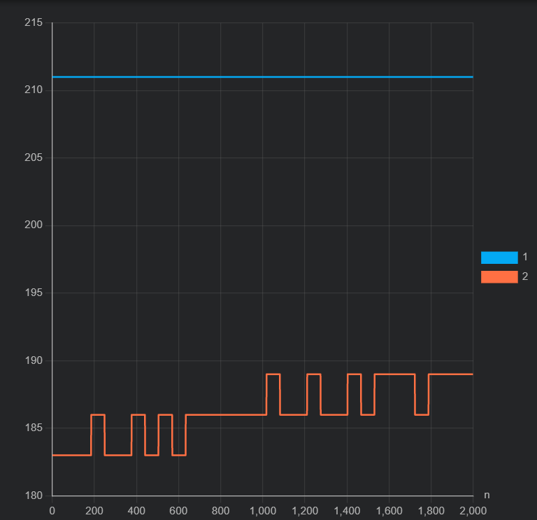
The disc has 20 slots so its 20 ticks per revolution. The analog output can vary between 0 to 255. So +- 2RPM is okay by me, I also want stability because it puts a lot of stress on the motor driver.
I was told that a PI controller is sufficient for most PID applications and the derivative term makes things jittery/noisy? So in the case of a PI controller, how would I counterbalance the P term without a D term?
It all depends on the tuning and the quality of your signal. If the signal has considerable noise, the derivative may indeed result in jittering.
But: a strong integral action will lead to overshoot and sluggish response. The derivative can counteract that.
It is important to find a set af values for p i and d where these actions cooperate. Wrong values may lead to ossilations, offsets, slow response, large overshoot...
Could you please tell me why the PID signal is oscillating like this even though the setpoint has not been reached and the P value is very small (0.01), with no I or D terms? The error is positive so the signal should keep increasing, but it keeps falling and I don't understand why?
The actual value fluctuates between 0 to 255. It is free running. I understand that there will be oscillation, just trying to figure out why. This is only a P controller, and the error is constantly positive as it hasn't hit the setpoint, so why does the output decrease occasionally? The reason I'm asking this is because I don't know if this is how a P controller normally behaves for motor speed control
It is normal that it will never reach the setpoint and will ossilate around a line below the setpoint.
The higher p, the closer to the setpoint...
I would hope the value sent to the motor is a bit more stable than between 0 and 255 after settling to a stable situation...
Why not actually read up on PID tuning, learn the theory and proceed as the professionals do, rather than consult random YT videos and hobby forum posts?
Edit to be clear: If you can set outputs to a resolution of 1/255=0.4% or read speeds to 1/60=1/60=1.7%, it will be hard to control to +/-2%. What if you need to set the speed at 211/20/60=70.3333 encoder clicks/sec needing 20.00% duty cycle and can only read 70 or 71 clicks, and produce 12/255 or 13/255 duty cycle? You'll get some slop due to integer resolution.
==
To produce a non-zero level of output, a P-only controller has to have some error to work with. That's what Kp does: output = kP*error It will seek towards error = output/kP.
An additional thing that could be biting you is that your count_per_sec variable is used both in your ISR and your main code without declaring it as volatile and without making a copy of it. Since you have it declared as float (which is a poor choice for a simple counter) you can not copy the entire variable atomically.
Wait, if you are reading the counts of a 20PPR encoder on a 211RPM motor (70.333Hz!!) at 60 Hz, there's only time for `211*20/60/60=1.17 counts/sample. Counts that size would fit easily in an 8-bit byte. You could use the counter in 8 bit mode and have plenty of headroom. And it would have terrible resolution: either 1 count in a cycle or 2 counts in a cycle.
You'd be far better off estimating speed using the 14ms or 14218us interval between your desired 70.3Hz encoder click rate.
Oops. The comment in the code is wrong. You are counting over a second (16000000/1024/(15624+1) = 1sec and planning for 211*20/60 = 70.333 counts/sec.
The counts_per_sec will still fit easily in an 8 bit counter/byte and have slow updates (1Hz) and report only integer RPMs of 70*60/20=210 and 71*60/20=213
Any PID using these low-resolution inputs will have problems with control. It is a GIGO problem.
You don't need to use these libraries, but look into the difference between frequency counting and frequency measuring: