Hello, I'm very new to these electronic and hardware stuff but i wanted to try and make a drum controller (tatacon).
I followed a guide that used an Arduino Micro and figured a Pro Micro should work. guide mentioned a 3.3v but i bought a 5v. My piezo sensor keeps reading something so i tried testing in one by one and it apparently it picks up some reading. I tried using a 1M ohm resistor but i don't know where to connect it and i'm worried i might need to buy a new microcontroller with a 3.3v output.
Here's the code i tried using to test :
const int ledPin = 13;      // led connected to digital pin 13
const int knockSensor = A0; // the piezo is connected to analog pin 0
const int threshold = 100;  // threshold value to decide when the detected sound is a knock or not


// these variables will change:
int sensorReading = 0;      // variable to store the value read from the sensor pin
int ledState = LOW;         // variable used to store the last LED status, to toggle the light

void setup() {
 pinMode(ledPin, OUTPUT); // declare the ledPin as as OUTPUT
 Serial.begin(9600);       // use the serial port
}

void loop() {
  // read the sensor and store it in the variable sensorReading:
  sensorReading = analogRead(knockSensor);

  // if the sensor reading is greater than the threshold:
  if (sensorReading >= threshold) {
    // toggle the status of the ledPin:
    ledState = !ledState;
    // update the LED pin itself:
    digitalWrite(ledPin, ledState);
    // send the string "Knock!" back to the computer, followed by newline
    Serial.println("Knock!");
  }
  delay(100);  // delay to avoid overloading the serial port buffer
}
When i connect the pro micro, the reading keeps saying "Knock!".
When i changed the code to some kind of value reading it either sends the highest value or just 0 then returns to 1023 and keeps going down until i press it again.
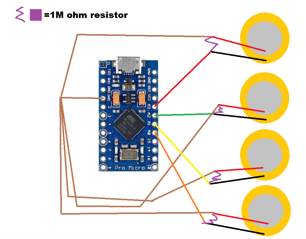
I'm so sorry for wasting you, @Railroader, and @jremington 's time.. I tried moving the power to GND and it worked flawlessly ? Thank you for trying to help. I did end up using the resistor by connecting the piezo sensor's negative and positive terminals with the resistor.
the arduino is a pro micro clone
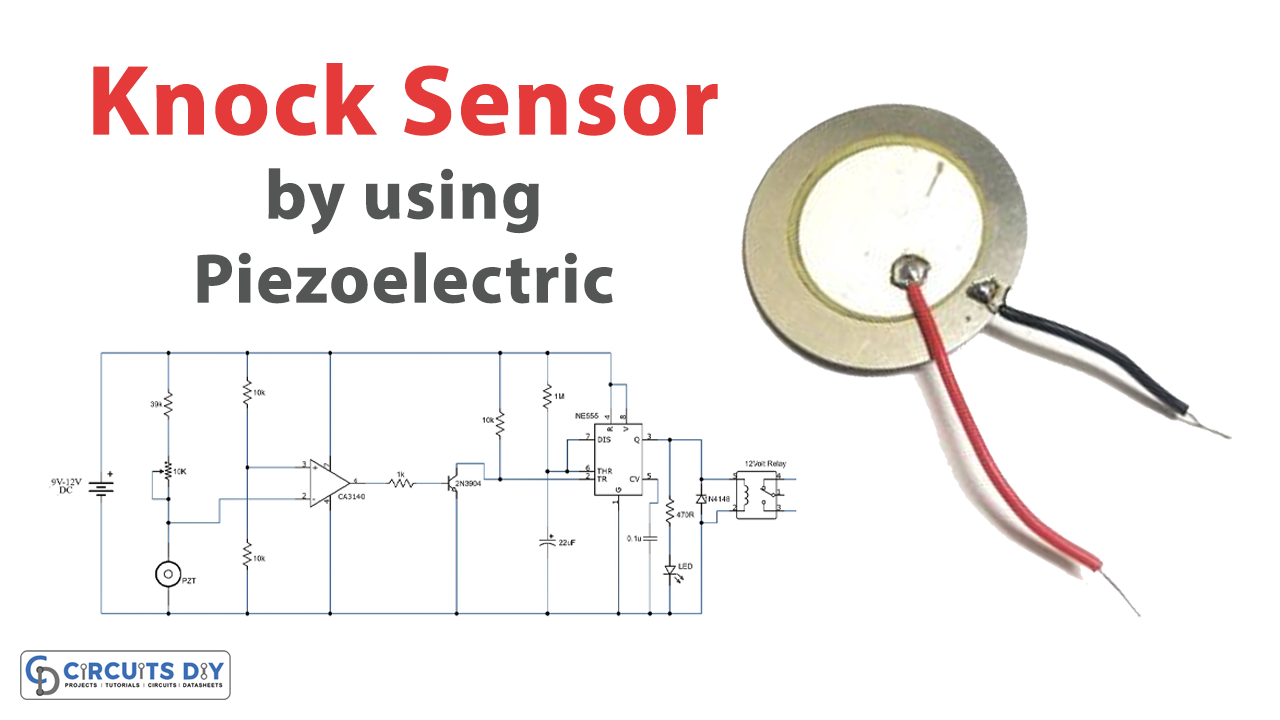
If you're still curious the guide is :
As for the code :
Schematics (i really tried, i don't know if this is proper, sorry) :
Tells me nothing, never played with them.
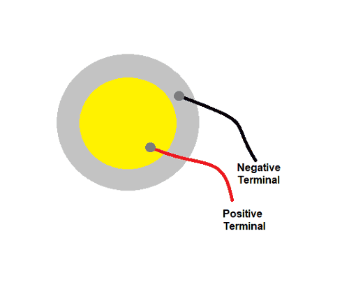
The piccture supplied by the OP was signed "+" resp "-" for the terminals and the polarity looked like wrong in the picture.
You might try experimenting with a piezo disk sometime!
The piezo disk bends or distorts when voltage is applied, and conversely, voltage is generated when the disk is bent. The polarity is usually irrelevant.
Picture of a hand drawn schematic is better if you don't have CAD program.
Hand drawn is quicker and only needs pen(cil) and ruler, multi-colour diagrams can be confusing.
Cut and pasting images, due to resolution can cause reading problems to.
Tip, Unless necessary make all wires horizontal or vertical with right angle joints rather than diagonal lines.
It just takes practice and observation of some of the simple circuits to get the hang of it.