Hi, im trying to make my first arduino project and will love a bit of critic and help.
I plan to do an plant sensor kit and waterer and control over a pair of DC LED drivers.
For the control over the power of the leds and wich ones i will turn on(two different sets), i plan to use a 4 relay module.
I also got at home some BC517 transistors, i thought maybe i could do a sistem to control which led lights i turn on with them but i dont know if they can resist up to 65V and 650mA current (the led drivers output),
will this be a good idea?
I am open to look also for another better solutions.
I will attach my diagram for better understanding, critics are very welcome.
Thanks for your time

Your BC517 will not work at 65v dc, their limit is about 30 or 40v -see its datasheet.
A good alternative would be a TIP122 Power Darlington transistor with can handle 100v, but it will generate a lot of heat, so needing a heatsink.
You will be better using a Logic Level Mosfet like a STP40NF10L or similar 100v device.
You could stick with the relay board, it would be easier to use / wire up.
The advantage of a transistor or mosfet is low switching noise/interference and the ability to use PWM to dim the leds etc.
Same with the motors transitor, no mention of its current, though you appear to be running it off the 5v line that runs the Arduino board, not a good idea to have a noisy motor on the same line and particulalry delicate input sensors.
What power supply are you intending to use for the Arduino board.
Hi [user]ricky101[/user], thank you so much for you time.
Thanks for your advice, will stick by the moment with the relays, as it is my first project will try to make it simple. As this way should work. But will take soon a look more in deep how MOSFET logic level works for later improvement, thanks for showing me it, i was a bit lost about how to control so big currents logically and cheaply.
Same with the motors transitor, no mention of its current, though you appear to be running it off the 5v line that runs the Arduino board, not a good idea to have a noisy motor on the same line and particulalry delicate input sensors.
What power supply are you intending to use for the Arduino board.
The motor is a small water pump and is rated 2,5 to 6 V, and the transistor i plan to put is the same i mentioned before, the BC517 as i got it at home(as i understand on its datasheet, Base Emitter On Voltage is 5V so should work, if im looking at the right parameter).
What you say about the noise of the motor and the sensors is also true, i dont thought about it, thanks so much!, maybe i can make some simple design to reduce it adding some diodes or something? or should i just dont take measurements while im watering?
I Actually dont have an power supply, was intending to use it conected thru usb to a rPi(to later try to get the sensors data on the rPi), and if dont worked cause it hadnt enought power, to buy a 9V 1A or 2A power supply.this will not be enought? What would you recommend?
Thanks again for your time
Hi,
Welcome to the forum.
Can you please post a copy of your circuit, in CAD or a picture of a hand drawn circuit in jpg, png?
NOT A FRITZY picture, it lacks so much important detail.
What are the transistor E B and C legs?
Why have you got the output of your relays wired so that one produces a short to your supply?
What is your supply?
Do you know how that DC plug works.
Please .. please please a circuit diagram of how you are connecting components and component lead and type labels please.
This may seem a hard thing to do, but it is a standard thing to produce when designing circuits.
A hand drawn circuit is all we need.
As I said earlier, a fritzy omits so much information when it comes to circuit function, its okay when showing how to assemble on protoboard, but hopeless at circuit description.
Thanks.. Tom.. ![]()
Hi TomGeorge thanks so much for your welcome, time, and response ![]()
Sorry because also is first time i use Fritzing and i couldnt find some simbols so i just used something similar, for example a AC-DC converter to use as the led drivers.
You are completely wright when you say the Fritz omits so much information, i thought it can replace a wire diagram but it cant, so i taked your advice and re made the circuit on paper, this helped me to find some fails in dc motor wiring and to see better what im building, really thanks.
I tried to make the diagram as simple and explained as i could, in top part is the light and power control part with the relays and a diagram of how the relay board is going to be wired, and in the bottom, the sensor input and water pump control. All 5V connectors are going to be wired to the arduino VCC.
if something needs to be remade or completed for better understanding, or further explanation is needed just say :D!

I also remade the wiring of the motor control

**edit: image links dont appeared
What is your supply?
i bought it on the internet as a AC 220V LED current DRIVER for 12x to 18x 3W leds, and it has an output of 36V-75V at 650mA that i assume auto regulate, for the LEDs being wired in serial.
What are the transistor E B and C legs?
From left to right as conected to breadboard, CBE
Do you know how that DC plug works.
The truth to be said, not really, i just suposed the board worked just with a specific current, but with a fast search i see is a bit more complex than that, if you know some good related post would be awesome.
Why have you got the output of your relays wired so that one produces a short to your supply?
I dont intend to have any short in the supply, maybe i dont explain well my diagram, in the newer one maybe is better explained what i intend to do.
Really thanks for your time and help and sorry for the newbie questions ![]() Niko
Niko
Hi,
Thanks for those. I'll get to look at them when I'm free.
If you use REPLY rather than QUICK REPLY you will have available an Attachment tag, so you can attach files to your message.
OPs images
Tom... ![]()
Hi,
A quick look and you will need to change you pump drive circuit, NPN can only work as what is called LOW SIDE switching.
Also if the LED is to be used as an indicator it needs to be in parallel with the motor.

The BC517 may have to big a volt drop to give you full pump power, so try it, but you may meed to go to a MOSFET as suggested earlier.
Tom... ![]()
Hi again Tom, thanks so much for the time you already spent helping me.
you are wright i wired really badly the motor, i confused the tipes of transistors and i put really badly the led, i feel ashamed
This project is now far bigger than i expected, without your advice to make wires TomGeorge i'm uderstanding way better everithing i'm wiring, really thanks, could i ask you which program u used for the NPN diagram? maybe next time i can make something nicer and cleaner than mi ugly hand drawings ![]() i tried fritz for it but dont feeled comfortable
i tried fritz for it but dont feeled comfortable
Sorry i dont answered you earlier because ive been working all day on the project trying to improve it, i added some more motors(4x12V Fans) i will controle by an arduino adafruit V1 shield that i bought for another project but ill use now(I was going to manage this manually, but i think is a good feature).
And using your scheme with another NPN transistor and connected another motor (12V fan with rpm sensor), i just changed the position of the info motor working led, is not connected to the Collector but to Base (I think should work also?) to be driven by 5V not 12V as the Fan.(thanks for the diagram, really clear)
And at last i also tried to wire up a PWM CPU intel Fan, but i see everywhere they go attached to PWM Ports, but all the adafruit shield goes over this ports, will it be possible to still control this motor or it will interfere with the adafruit shield?
I also have a lots of questions regarding the interference of the sensor with the motors, because im just adding more and more noise(dc motors)..., as i understand, the 12V motors i just added should not interfere with the sensors as the will have their own 12V power source only for motors(i put it as the battery in the fritz)(the arduino will be powered by usb), and the sensors go out of the 5V arduino VCC. But if i used the source for all the motors (the ones on the shield and the transmiter controlled ones) and the arduino, will interefere in the sensors? here i cant use the same approach as is in the water pump one, as i must sensor temp while i use the fans.

edit*photos still not showing, added links
Hi,
Your diagram shows the BC517 the wrong way around, the emitter goes to gnd and the collector goes to the motor.
I forgot the back EMF protection diode across the motor too.
Also put your indicator LED from output to gnd rather than in series with the base.
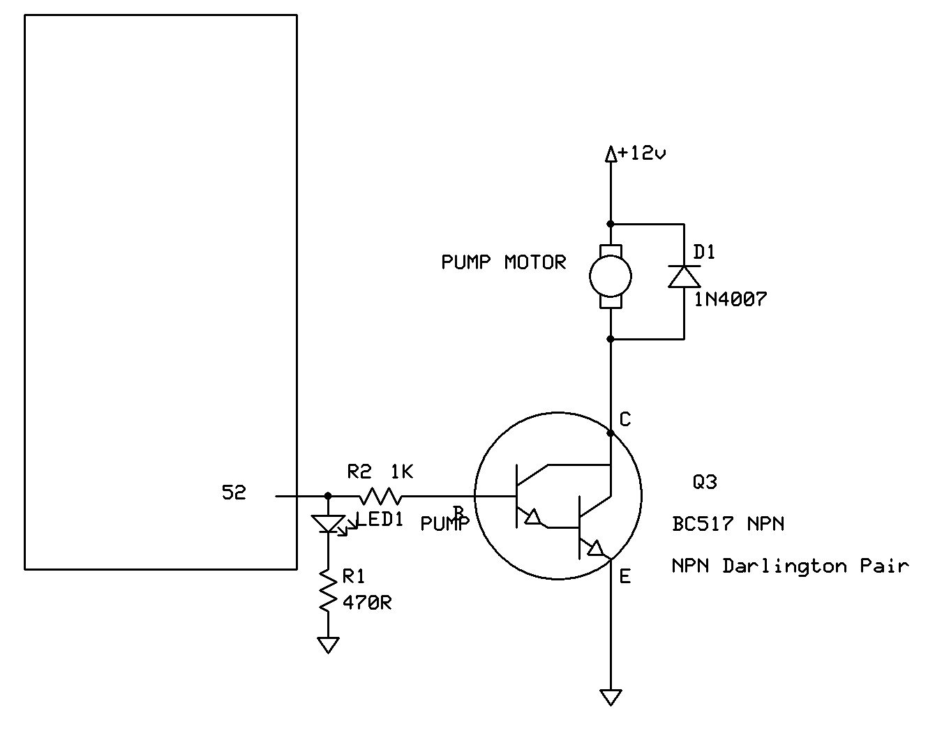
Keep going mate, your learning. you first attempt at circuit diagram is really good, excellent labelling.
Tom... ![]()
Thanks again for your awesome diagram! is very helpfull ![]()
I just updated the fritz changing the Led to its new place and wiring well the NPN based on your diagram (i moved it before, and dont wire it well in its new position)
I supose the led is beter in paralel to the NPN to not create a voltage drop at base.
I also conected the negative of the power supplies to the ground of the arduino. i dont know if this is a good idea or just will create more interferences and noise at the sensors and is better to dont put them together
Thanks again for your time ,patience, and kind words
but i still think the diagram could be way better ![]() tomorrow will try to search for a program to make it by computer complete, cleaner, and with all this changes im doing
tomorrow will try to search for a program to make it by computer complete, cleaner, and with all this changes im doing
I uploaded the img this time to postimege, lets see if this time shows ![]()
https://postimg.org/image/5rjcl1btl/
Hi,
I also conected the negative of the power supplies to the ground of the arduino. i dont know if this is a good idea
A very good idea, otherwise you will not have current flow for the base circuit and current flow for the motor circuit.
Tom... ![]()
Thanks for your reply,
about the noise and interfering in this mix of lines and different voltages, i should have no worries with the designed circuit right now?
any suggested help with the topic or some good related post would be awesome, if i search "noise sensors" everithing is related noise measuring devices
I can understand if you have no idea about the topic or dont want to help me more, im new in this of writing in forums but maybe opening another thread in a more specific topic i could find better this specific help or should i wait some time to see if somebody else helps?
Hi,
Using 0.1uF caps across the motor terminals will help.
Keeping your motor and other wiring clear of the lower level signal wiring.
Tom.... ![]()
Really thanks TomGeorge for all your support,
I created a post to update the advance on the project, you can take a look at:
I uploaded your sketchs to the post also, if you have any problem with it i will remove them
Remeber your help made it possible
Hi,
No problem with my diagrams.
If you use REPLY rather than QUICK REPLY and it has an attachment facility, so you can post your files as an attachment.
Tom... ![]()