Hi ,
Need a little help. Built the induction heater from mindchallenger website. Using an UNO board in the attempt to automatically control unit. What I'm trying to do is take a value of approx. 1.900v and maintain this as a setpoint. The pwm output from the UNO starts off somewhere around a value of 30(600mv). I found these values by running the unit in a a manual mode and checking the in-out with a DVM. As the heater runs under load , the inductance changes in the tank circuit, causing a phaseshift in the control circuit. I want to hold a setpoint using a changing input. Have tried the Arduino PID sketch, using it as a P controller. Went through many control parameters with no usable results. Tried some threshold coding . Been working on this control issue for months, checking blogs, forums and searching the web. Can use the heater in manual mode, but want the next step up.I've built other simple equipment ran by Uno boards , used Mega boards to control industrial machines. Programming is fun and a challenge to get exactly right. I just need help to get this controller headed in the right direction. Open for suggestions. Thanks
Need more detail. How exactly are you generating a feedback signal and feeding it into the Arduino? What control code have you tried, and what was wrong with the results?
You're trying to maintain a phase-locked loop? I don't understand how that relates to the input (voltage?) or the (pwm?) output. Perhaps if you could describe the nature of the input signal you're trying to handle, and how that relates to the output you're trying to generate, it would be more obvious what the problem is.
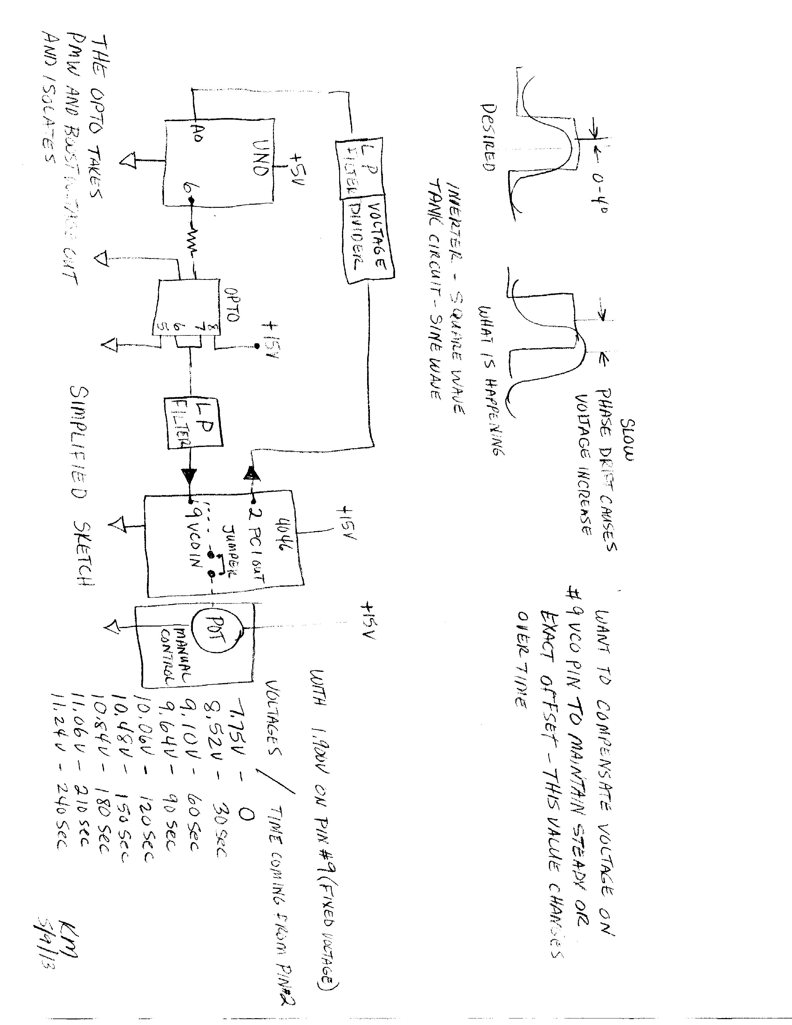
Thanks for writing. The input signal for Arduino comes from pin 2(PC1out) from a 4046 chip. If you will, look up mindchallenger.com website / induction heater. There is a schematic listed as uP-PLL resonance driver. Use a reference. The output dc voltage is proportional to phase difference. I'm taking this output,
using it as a setpoint. This voltage goes through a divider with a filter. This is introduced to input of
Uno at aprox. 1.900v (at resonance). In order to get this level, I feed a pwm signal (aprox. 12 %)
through an optoisolator which bumps my voltage higher than the Arduino is capable to the VCO on the 4046. I can use a pot to set the pwm (fixed). When the frequency changes in the work coil, the value starts slowly changing the phase angle, dropping the VCO voltage.I want the Arduino to compensate . It is still a PLL, but will not stay fixed to an exact angle. Used P controller , tried both,direct and reverse directions(experimenting). Thinking maybe put in a softstart on VCO and then shift over to Pcontroller. Going to keep trying until it's working . Sometimes it's hard being so picky, but I know it can be done! Open to all suggestions and guidance.
Thanks.
I get the general idea, but a schematic would be helpful. Hand drawn is fine. Also graphs of how the PLL output varies with time and with PWM might help.
kmosely:
a 4046 chip ... If you will, look up
Could you provide links? That would save me time looking it up for myself, and possibly avoid me finding the wrong thing.
Hi,
Do not have any voltage/time graph work. That is a good idea. Do have numbers to look at along with a simple sketch. Take a look and see if this is of some help.
Thanks dc42,
I will do test for control input /output of 4046 chip. Will do graph and spreadsheet to better understand where I'm going. From this data, should be able to come up with a constant to use in program to maintain a tight control of phase. My concern is that, changing powerlevel on inverter/tank circuit may have an influence on the VCO in controller chip, throwing everything out of wack. Don't know if responce will be linear. Guess I have a lot of testing to do. Was hoping one of the many forum readers had a project very similar, and could share insight.
Once again,
Thanks
Nice project!
What about the propagation delay in the signal chain between the 4046's phase_comp output - filter - aruino's ADC - arduino PID - and the PWM based DAC / filter which output you are feeding back into 4046's VCO? (prop delay from 4046's pin PC1OUT ----> pin VCOIN ?)
Frankly, I would go with a pic24/dspic33 for such a design ![]()
Also the low-pass filters - I would probably go into higher orders (..more delays ![]() ).. Even a simple PLL freq synth with 4046 required better filters there, afaik (back in 80ies).
).. Even a simple PLL freq synth with 4046 required better filters there, afaik (back in 80ies).
With 65kHz res freq (153usec) I would guess (just a guess, plz) the propagation delay shall be lower than 153usec (because your PLL divider = 1)..
Thanks for your responce. What is your reason to use a pic24? I'm just soaking up and digesting all the feedback that I get, asking questions to learn.
Hi guys, I'm back with great news. Solved my problem . Did have a problem with propagation delay. This got me thinking, delay is time relative. PI control program that I used could'nt keep the value as close as I wanted. Tried an output control filter with PI program, tried all concievable parameters. I gave it an honest try(and try and try and......).
The solution was really very simple(finally!). I used an example if else program( changed numbers). Just checked my voltage on oscillator pin #2 (voltage created by phase difference while machine is in manual mode). Then I program this as the threshold number. When the unit is powered, a voltage is sent from pin 2, through a divider, this is the analog input to the arduino. With threshold not met, I have a digital output pin that goes high. This voltage goes through a voltage divider, dropping it down to approx. 2.25 volts. Then, this voltage is sent through a low pass filter( slow charging circuit) with a big fat capacitor. The voltage is the bled down by the on/off of the threshold setting(comparator circuit?)
The off and on action is fast. It has a very smooth output.It feeds pin # 9- oscillator control voltage. I can change the threshold and the output reponds accordingly. Could'nt believe it! Fluctuations of a few millivolts
Output with analog meter in low range and the needle does'nt quiver or move. This really works. Can post a schematic of control circuit if anyone is interested. Thanks to the people that did respond. You guys gave me things to consider and ponder.
Thanks.
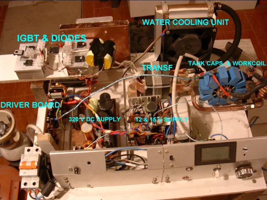
Hi friends: I hope that so many days from last post is not too late!... I'm also traying to build the mindchallenger Induction Heater, I put a picture, for more than a year, and a mountain of transistors and components burned, and would like to go up for the 10kw unit using that uP to control the PLL, but have no idea about programming or pic's... I even contacted with the author of that project, asking for him the code for the arduino, but regretably he told me he is now in other kind of projects and no longer has it. After googling for days I finally found this forum and it seems Kmosely got some solution! Please, I would like, if possible, you share with me information or code to help me to build the same... Thanks in advance!.
Cab u send me a schematic of your control circuit for the pll resonance lock for the induction heater
Sman,
Are you expecting a person who solved his own problem over 4 years ago, and hasn't posted since, to still be monitoring this topic?