PLX-DAQ version 2 - now with 64 bit support! (and further new features)

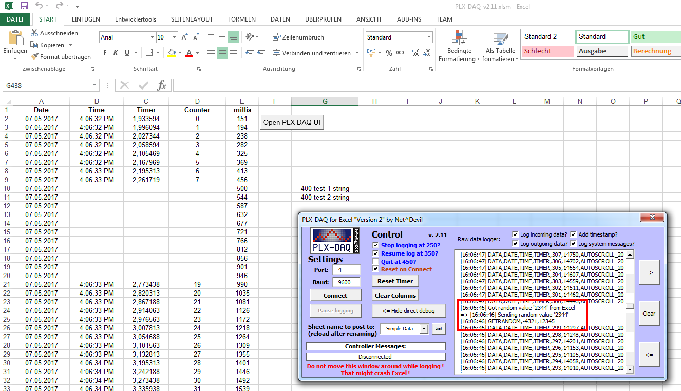
Hello everybody! I'm really new in Arduino. I have a project going on right now about the MPU6050 gyroscope and accelerometer sensor. I was trying to gather the data and plot in PLX-DAQ in real time but for some reason the PLX-DAQ is not showing any values in the table. Also, the values that's coming from the sensor is reading in Display direct debug window but nothing is showing up in the excel spreadsheet. I just want the raw data from coordinate x, y, z displaying and graphing realtime in excel spreadsheet. Below is my program and some screens shots. It would be a very big help if someone can help me with this one. Thank you everybody.

#include <Wire.h>

long gyroX, gyroY, gyroZ;
float rotX, rotY, rotZ;

void setup() {
Serial.begin(9600);
Serial.println("CLEARDATA");
Serial.println("LABEL,X=,Y=,Z=");

Wire.begin();
setupMPU();
Serial.println("RESETTIMER");
}

void loop() {
recordGyroRegisters();
Serial.print("Gyro (deg/sec)");
Serial.print(" X=");
Serial.print(rotX);
Serial.print(" Y=");
Serial.print(rotY);
Serial.print(" Z=");
Serial.println(rotZ);
delay(100);
}

void setupMPU(){
Wire.beginTransmission(0b1101000); //This is the I2C address of the MPU (b1101000/b1101001 for AC0 low/high datasheet sec. 9.2)
Wire.write(0x6B); //Accessing the register 6B - Power Management (Sec. 4.28)
Wire.write(0b00000000); //Setting SLEEP register to 0. (Required; see Note on p. 9)
Wire.endTransmission();
Wire.beginTransmission(0b1101000); //I2C address of the MPU
Wire.write(0x1B); //Accessing the register 1B - Gyroscope Configuration (Sec. 4.4)
Wire.write(0x00000000); //Setting the gyro to full scale +/- 250deg./s
Wire.endTransmission();
Wire.beginTransmission(0b1101000); //I2C address of the MPU
Wire.write(0x1C); //Accessing the register 1C - Acccelerometer Configuration (Sec. 4.5)
Wire.write(0b00000000); //Setting the accel to +/- 2g
Wire.endTransmission();
}

void recordGyroRegisters() {
Wire.beginTransmission(0b1101000); //I2C address of the MPU
Wire.write(0x43); //Starting register for Gyro Readings
Wire.endTransmission();
Wire.requestFrom(0b1101000,6); //Request Gyro Registers (43 - 48)
while(Wire.available() < 6);
gyroX = Wire.read()<<8|Wire.read(); //Store first two bytes into accelX
gyroY = Wire.read()<<8|Wire.read(); //Store middle two bytes into accelY
gyroZ = Wire.read()<<8|Wire.read(); //Store last two bytes into accelZ
processGyroData();
}

void processGyroData() {
rotX = gyroX / 131.0;
rotY = gyroY / 131.0;
rotZ = gyroZ / 131.0;
}

Hi clomo,

you were pretty close to get it working but you missed using the DATA command :wink:
CLEARDATA is good, LABEL is correct as well. RESETTIMER is not necessary since the timer gets reset on startup anyways (but won't do no harm to call it, thus don't worry about it).

The issue is, that your loop is sending data the way a human would read it. Not in a way PLX DAQ can read it.

You should change yours:

void loop() {
  recordGyroRegisters();
  Serial.print("Gyro (deg/sec)");
  Serial.print(" X=");
  Serial.print(rotX);
  Serial.print(" Y=");
  Serial.print(rotY);
  Serial.print(" Z=");
  Serial.println(rotZ);
  delay(100);
}

into

void loop() {
  recordGyroRegisters();
  Serial.println( (String) "DATA," + rotX + "," + rotY + "," + rotZ);
  delay(100);
}

and that's it already :slight_smile:
That way the line in DirectDebugWindow will read e.g., "DATA,0.21,0.06,0.08"
And that will be interpreted by PLX DAQ because of the DATA at the beginning, afterwards every value will be posted to the columns (as many columns as data is given, thus 3 columns in this case).

If you have any further questions please feel free to ask :slight_smile:

Greetings!

NetDevil:
Hi clomo,

you were pretty close to get it working but you missed using the DATA command :wink:
CLEARDATA is good, LABEL is correct as well. RESETTIMER is not necessary since the timer gets reset on startup anyways (but won't do no harm to call it, thus don't worry about it).

The issue is, that your loop is sending data the way a human would read it. Not in a way PLX DAQ can read it.

You should change yours:

void loop() {

recordGyroRegisters();
  Serial.print("Gyro (deg/sec)");
  Serial.print(" X=");
  Serial.print(rotX);
  Serial.print(" Y=");
  Serial.print(rotY);
  Serial.print(" Z=");
  Serial.println(rotZ);
  delay(100);
}


into


void loop() {
  recordGyroRegisters();
  Serial.println( (String) "DATA," + rotX + "," + rotY + "," + rotZ);
  delay(100);
}


and that's it already :)
That way the line in DirectDebugWindow will read e.g., "DATA,0.21,0.06,0.08"
And that will be interpreted by PLX DAQ because of the DATA at the beginning, afterwards every value will be posted to the columns (as many columns as data is given, thus 3 columns in this case).

If you have any further questions please feel free to ask :)

Greetings!

NetDevil, I really appreciate your help! Thank you very much!

Hello Netdevil, I have another problem quite similar to the one that I have above about the PLX-DAQ not reading into the excel spreadsheet. This time the code is about calculating angle in degrees in MPU 6050 I tried to do similar solution above. I added this command "Serial.println((String)"DATA," + "/t" + "," + " ");"but the excel still not reading it. I spent few hours trying to edit the program but I just couldn't make it work. Below is the code and some screen shots. Thank you again for the assistance.

#include "Wire.h"

#include "I2Cdev.h"
#include "MPU6050.h"

// class default I2C address is 0x68
// specific I2C addresses may be passed as a parameter here
// AD0 low = 0x68 (default for InvenSense evaluation board)
// AD0 high = 0x69
MPU6050 accelgyro;

int16_t ax, ay, az;
int16_t gx, gy, gz;

#define LED_PIN 13
bool blinkState = false;

// accelerometer values
int accel_reading;
int accel_corrected;
int accel_offset = 200;
float accel_angle;
float accel_scale = 1; // set to 0.01

// gyro values
int gyro_offset = 151; // 151
int gyro_corrected;
int gyro_reading;
float gyro_rate;
float gyro_scale = 0.02; // 0.02 by default - tweak as required
float gyro_angle;
float loop_time = 0.05; // 50ms loop
float angle = 0.00; // value to hold final calculated gyro angle

// time stamp variables
int last_update;
int cycle_time;
long last_cycle = 0;

void setup() {
// join I2C bus (I2Cdev library doesn't do this automatically)

Wire.begin();

// initialize serial communication
Serial.begin(9600);
Serial.println("CLEARDATA");
Serial.println("LABEL,DegreesC");

// initialize device
Serial.println("Initializing I2C devices...");
accelgyro.initialize();

// verify connection
Serial.println("Testing device connections...");
Serial.println(accelgyro.testConnection() ? "MPU6050 connection successful" : "MPU6050 connection failed");

// configure Arduino LED for
pinMode(LED_PIN, OUTPUT);
}

void loop(){
// read raw accel/gyro measurements from device
accelgyro.getMotion6(&ax, &ay, &az, &gx, &gy, &gz);
Serial.println((String)"DATA," + "/t" + "," + " ");

// accelerometer_X_Axis angle calc
accel_reading = ax;
accel_corrected = accel_reading - accel_offset;
accel_corrected = map(accel_corrected, -16800, 16800, -90, 90);
accel_corrected = constrain(accel_corrected, -90, 90);
accel_angle = (float)(accel_corrected * accel_scale);
Serial.print(accel_angle);
Serial.print("\t");

// gyro_Y_Axis angle calc
gyro_reading = gy;
gyro_corrected = (float)((gyro_reading/131) - gyro_offset); // 131 is sensivity of gyro from data sheet
gyro_rate = (gyro_corrected * gyro_scale) * -loop_time; // loop_time = 0.05 ie 50ms
gyro_angle = angle + gyro_rate;

// print values to serial monitor for checking
Serial.print(gyro_angle);
Serial.print("\t");
Serial.print(" ");

// blink LED to indicate activity
blinkState = !blinkState;
digitalWrite(LED_PIN, blinkState);

//timestamp
time_stamp();
}
void time_stamp(){
while ((millis() - last_cycle) < 50){
delay(1);
}
// once loop cycle reaches 50ms, reset timer value and continue
cycle_time = millis() - last_cycle;
last_cycle = millis();
}

Angle Measurement In Degrees.pdf (155 KB)

I'm sorry here is the original code for calculating the angles, The code above was already been edited by me. Any help would be appreciated! Thank you again.

#include "Wire.h"

// I2Cdev and MPU6050 must be installed as libraries, or else the .cpp/.h files
// for both classes must be in the include path of your project
#include "I2Cdev.h"
#include "MPU6050.h"

// class default I2C address is 0x68
// specific I2C addresses may be passed as a parameter here
// AD0 low = 0x68 (default for InvenSense evaluation board)
// AD0 high = 0x69
MPU6050 accelgyro;

int16_t ax, ay, az;
int16_t gx, gy, gz;

#define LED_PIN 13
bool blinkState = false;

// accelerometer values
int accel_reading;
int accel_corrected;
int accel_offset = 200;
float accel_angle;
float accel_scale = 1; // set to 0.01

// gyro values
int gyro_offset = 151; // 151
int gyro_corrected;
int gyro_reading;
float gyro_rate;
float gyro_scale = 0.02; // 0.02 by default - tweak as required
float gyro_angle;
float loop_time = 0.05; // 50ms loop
float angle = 0.00; // value to hold final calculated gyro angle

// time stamp variables
int last_update;
int cycle_time;
long last_cycle = 0;

void setup() {
// join I2C bus (I2Cdev library doesn't do this automatically)
Wire.begin();

// initialize serial communication
Serial.begin(9600);
Serial.println("CLEARDATA");
Serial.println("LABEL,Angle");
// initialize device
Serial.println("Initializing I2C devices...");
accelgyro.initialize();

// verify connection
Serial.println("Testing device connections...");
Serial.println(accelgyro.testConnection() ? "MPU6050 connection successful" : "MPU6050 connection failed");

// configure Arduino LED for
pinMode(LED_PIN, OUTPUT);
}

void loop(){
// read raw accel/gyro measurements from device
accelgyro.getMotion6(&ax, &ay, &az, &gx, &gy, &gz);

// accelerometer_X_Axis angle calc
accel_reading = ax;
accel_corrected = accel_reading - accel_offset;
accel_corrected = map(accel_corrected, -16800, 16800, -90, 90);
accel_corrected = constrain(accel_corrected, -90, 90);
accel_angle = (float)(accel_corrected * accel_scale);
Serial.print(accel_angle);
Serial.print("\t");

// gyro_Y_Axis angle calc
gyro_reading = gy;
gyro_corrected = (float)((gyro_reading/131) - gyro_offset); // 131 is sensivity of gyro from data sheet
gyro_rate = (gyro_corrected * gyro_scale) * -loop_time; // loop_time = 0.05 ie 50ms
gyro_angle = angle + gyro_rate;

// print values to serial monitor for checking
Serial.print(gyro_reading);
Serial.print("\t");
Serial.print(gyro_corrected);
Serial.print("\t");
Serial.print(gyro_angle);
Serial.print("\t");
Serial.println(" ");

// blink LED to indicate activity
blinkState = !blinkState;
digitalWrite(LED_PIN, blinkState);

//timestamp
time_stamp();
}
void time_stamp(){
while ((millis() - last_cycle) < 50){
delay(1);
}
// once loop cycle reaches 50ms, reset timer value and continue
cycle_time = millis() - last_cycle;
last_cycle = millis();
}

I figured out the answer thank you so much!!!! :slight_smile:

Hello Netdevil, I am using your software (2.10) to move data to and from arduino with success however when I run another macro that manipulates the data your macro freezes. Is there a way that they both can run simultaneously or give control back and forth? Using windows 7 and 32bit excel.

Thanks!

NetDevil:
Hey guys. Well it's been a while - nearly 2 months! But there is a new version available now! I did some groundwork and tried to tidy up a lot of code but in the end I'm just half done ... that's why I thought I might release the updates I already have and keep the rest for later :wink: And well there are quite a few new features!


What's new in "Version 2.11" aka Change log:

  • Extended DATA command by the parameter AUTOSCROLL_XY. Autoscroll will automatically scroll your Excel sheet along with each new row of data which is read and posted. XY can be replaced by any number (e.g., 20) to control how many additional lines should be shown above as well during scrolling.
  • Added a new function: GetRandom(min,max). It basically just returns a random number between min and max. Very useful if you need a random number for Arduino's randomSeed() to be initialized
  • Added several features to the direct debug window. The size can now be increased or decreased (to a certain extend), content can be cleared and you can decide what you want to log: incoming data, outgoing data, system data. Also a time stamp can be added if wanted.
  • Added a default line break after all data send to the Arduino. Thus no more delays are necessary before or after get/set calls. In order to read incoming data one should use either Serial.readStringUntil(10); or Serial.readStringUntil(10).toInt(); or Serial.readStringUntil(10).toFloat(); from now on
  • Optimized the way Excel processes multiple incoming lines of data for better performance
  • There are some new parameters which can be changed on the (hidden) settings sheet in Excel. Those "Expert Configs" should be handled with care. They are about the buffer sizes for your COM port. In case you decide to spam massive amount of data to Excel and increase the baud rate you might experience data loss. Try increasing the buffer sizes then.
  • Added a "PowerDemos" directory with some nice (at least I think so) demos. First demo is a moving self updating graph visualizing data from the Arduino.
  • Updated the Beginners Guide to reflect all new commands - and optimized the formatting as well
  • Updated the default sketch to include the new commands

Backlog for next version(s):

  • find a solution for Excel crashing when moving the window around while logging. Priority: low ; Workaround: don't move window while logging ; Status: clueless...
  • Double check if issue above existed in PLX DAQ v1 as well. In case yes => we are screwed
  • Rework API calls and general COM port communication handling for better stability. Very promising example to be found here. Works with up to 2.000.000 baud

Guideline to migrate from old version to new one ==> see Beginners Guide attached

Image-Link: http://www.freebie-base.de/Pics/PLX_DAQ_v2.11.png
(hosted on my server, no traffic hijack)

Can you please fix the links. None of them is working.
Thanks in advance

simon_126:
Can you please fix the links. None of them is working.
Thanks in advance

Hi Simon,

what links aren't working exactly? The one's to the image is working correctly ( http://www.freebie-base.de/Pics/PLX_DAQ_v2.11.png ) as does the link to the "promising example".

Do you mean the underlined words and sentences in the text? Those are no links but just highlighted text to better show the most significant changes in the new version.

Explainations to the new features can most likely be found in the Beginners Guide (see Post here for most recent version in the attachments)

Greetings

Hi, I have a problem with the v2.11, I have Windows 10, Excel 2016, when I clic Connect, after a while Excel stops and close.

Alejandro561:
Hi, I have a problem with the v2.11, I have Windows 10, Excel 2016, when I clic Connect, after a while Excel stops and close.

Hi Alejandro,

could you give me a bit more detail? Are you already sending data from your Arduino to PLX DAQ? Is incoming data shown in the DirectDebug window? Is data being posted to Excel sheet already? And (maybe most important) what baud rate are you using?

NetDevil:
Hi Simon,

what links aren't working exactly? The one's to the image is working correctly ( http://www.freebie-base.de/Pics/PLX_DAQ_v2.11.png ) as does the link to the "promising example".

Do you mean the underlined words and sentences in the text? Those are no links but just highlighted text to better show the most significant changes in the new version.

Explainations to the new features can most likely be found in the Beginners Guide (see Post here for most recent version in the attachments)

Greetings

I have tried many times to download PLX DAQ v2.11, 16 to be correct. Right at the end, it says file corrupted, couldn't be downloaded and etc. I really need that scroll down function and much more that you implemented to the original one. Please if that is possible reupload install files or upload them on another server. For the time you are the only distributor of it.

simon_126:
I have tried many times to download PLX DAQ v2.11, 16 to be correct. Right at the end, it says file corrupted, couldn't be downloaded and etc. I really need that scroll down function and much more that you implemented to the original one. Please if that is possible reupload install files or upload them on another server. For the time you are the only distributor of it.

Hi Simon,

the download is working fine for me, same for unpacking the zip file.
Nevertheless I uploaded the latest version here as well => http://freebie-base.de/Stuff/PLX-DAQ-v2.11.zip <=
Please post feedback whether it is working or not.
Thanks.

FYI: I don't have any problem with either link.

Pete

First of all, problem regarding link was my mistake at the office Kerio Control was ignoring download. When I tried download PLX from URLs everything was just perfect.
But second problem may be I am doing wrong can't get cell info from excel.

Serial.println("CELL,GET,B3,");
cell_num=Serial.read();// this command reads the sell value from the specified cell

//now return this namber to EXCELL:
Serial.print("DATA,TIME,");
Serial.print(bla);
bla=random(1,100);
Serial.print(",");
Serial.print(cell_num);
Serial.print(",");

But in excel instead og providing info from B3 cell it just prints in consequent columns GET CELL B3

What I am doing wrong. Really need your help

Hi guys, I need a little help here. I tried the default sketch given and together with the latest PLX-DAQ version 2.11. I noticed that the AUTOSCROLL is not functioning. The excel does not scroll automatically when new data received. I am using Office Excel 2007. Can anyone guide me? Thanks

simon_126:
But second problem may be I am doing wrong can't get cell info from excel.

Serial.println("CELL,GET,B3,");

cell_num=Serial.read();// this command reads the sell value from the specified cell

//now return this namber to EXCELL:
Serial.print("DATA,TIME,");
Serial.print(bla);
bla=random(1,100);
Serial.print(",");
Serial.print(cell_num);
Serial.print(",");


But in excel instead og providing info from B3 cell it just prints in consequent columns GET CELL B3

Hi Simon,

your code needs some rework.
First of all, make sure to end your commands to PLX DAQ with "println" instead of "print". Plus there is no need to add a final "," at the end of the statement.
And you use the variable "bla" before assigning a random value to it, better to switch it around :wink:

My rework suggestion is:

Serial.println("CELL,GET,B3"); // <= remove ","
cell_num= Serial.readStringUntil(10).toInt(); // <= new read function


Serial.print("DATA,TIME,");
bla=random(1,100); // <= switched command
Serial.print(bla); // <= switched command
Serial.print(",");
Serial.println(cell_num); // <= changed to "println"
//Serial.print(","); <<== ignore

dummy55555:
Hi guys, I need a little help here. I tried the default sketch given and together with the latest PLX-DAQ version 2.11. I noticed that the AUTOSCROLL is not functioning. The excel does not scroll automatically when new data received. I am using Office Excel 2007. Can anyone guide me? Thanks

Hi dummy,

sorry to say but the scroll function was added in Office 2013. Therefore no scrolling is possible in your version 2007...

I googled the issue and there was a dirty workaround in earlier versions of Excel. If you are familiar with Excel / VBA please try pressing Alt+F11 to open the code editor, search for the AUTOSCROLL part and replace with the following:

'## Check for AUTOSCROLL command and handle
If (InStr(1, UCase(DataVal(x)), "AUTOSCROLL_", vbBinaryCompare) >= 1) Then
    DontPostDataThisIteration = True ' Autoscroll will not be posted to sheet
    If (ActiveSheet.Name = WStoUse.Name) Then
        '## Autoscroll command checks should only be done if the currently active sheet is the sheet where data is pasted to
        '## Autoscroll command was added in Office 2013 (version 15.0) - dont use for earlier versions)
        Dim offset As String
        offset = Trim(Mid(DataVal(x), InStr(1, DataVal(x), "AUTOSCROLL_", vbBinaryCompare) + Len("AUTOSCROLL_"))) 'get value right side of "AUTOSCROLL_"
        If (IsNumeric(offset)) Then
            If ((row - offset) >= 1 And (row - offset) <= ActiveSheet.Rows.Count) Then 'if row - offset is too low (< 0) or too high ( > max row possible) set to row
                Application.Goto Range("A" & Range("A" & Rows.Count).End(xlUp).row - offset)
            Else
                Application.Goto Range("A1")
            End If
        End If
    End If
End If

I was not able to check the full code, however the workaround should basically work (it does with Excel 2013 on my PC).

Would be great to get some feedback from you

Greetings

Hi NetDevil,

The code works in excel 2007.
THanks alot for your help. :slight_smile:

Hi, thanks for the really useful DAQ.

I'm having trouble sampling data every 100 ms (well I'm in fact sampling 4 signals). Is there a limit to that?

I've tried increasing the data rate to 128000 (instead of the default 9600 in the original file I had) thinking that it would do the trick but Excel just crashes. I get a feeling that when it does crash it's because the data is not being written at the specified rate (here 10 Hz).

I'm using a 2013 version of Excel on a Win 7 64 bits system.