I'm new to Arduino and fairly clueless to this world in general.
I'm trying to get ATrappmann's PN5180 github resource to work. While the code compiles, loads, and appears to run correctly, I've been unable to get the hardware to recognize any ISO 15693 cards. I've copied the coding, wiring, and hardware exactly (I think). I'm unsure what level shifter is being used in the github wiring but I'm using a I2C-LOGIC-MD-5PC-SCZW (Amazon link here).
I've confirmed continuity on all the solder joints and have tried to check voltage. I read 5 and/or 3.3 at various connections but have no idea what voltage should be reading where or when.
Any ideas on how to effectively start troubleshooting this? Aside from importing the entire zip file, is there something else that needs to be set up to allow the programs to run correctly?
Jim-p: The serial monitor is looping the result of "*** No card detected!" I can post a screenshot of the serial monitor dialogue when I get home from work.
TomGeorge: Sorry, see below:
// NAME: PN5180-FeliCa.ino
//
// DESC: Example usage of the PN5180 library for the PN5180-NFC Module
// from NXP Semiconductors.
//
// Copyright (c) 2018 by Andreas Trappmann. All rights reserved.
// Copyright (c) 2019 by Dirk Carstensen.
// Copyright (c) 2020 by CrazyRedMachine.
//
// This file is part of the PN5180 library for the Arduino environment.
//
// This library is free software; you can redistribute it and/or
// modify it under the terms of the GNU Lesser General Public
// License as published by the Free Software Foundation; either
// version 2.1 of the License, or (at your option) any later version.
//
// This library is distributed in the hope that it will be useful,
// but WITHOUT ANY WARRANTY; without even the implied warranty of
// MERCHANTABILITY or FITNESS FOR A PARTICULAR PURPOSE. See the GNU
// Lesser General Public License for more details.
//
// BEWARE: SPI with an Arduino to a PN5180 module has to be at a level of 3.3V
// use of logic-level converters from 5V->3.3V is absolutly neccessary
// on most Arduinos for all input pins of PN5180!
// If used with an ESP-32, there is no need for a logic-level converter, since
// it operates on 3.3V already.
//
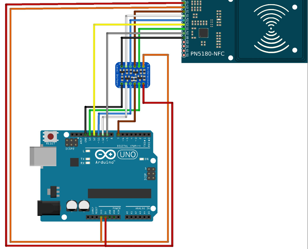
// Arduino <-> Level Converter <-> PN5180 pin mapping:
// 5V <--> 5V
// 3.3V <--> 3.3V
// GND <--> GND
// 5V <-> HV
// GND <-> GND (HV)
// LV <-> 3.3V
// GND (LV) <-> GND
// SCLK,13 <-> HV1 - LV1 --> SCLK
// MISO,12 <--- <-- MISO
// MOSI,11 <-> HV3 - LV3 --> MOSI
// SS,10 <-> HV4 - LV4 --> NSS (=Not SS -> active LOW)
// BUSY,9 <--- BUSY
// Reset,7 <-> HV2 - LV2 --> RST
//
// ESP-32 <--> PN5180 pin mapping:
// 3.3V <--> 3.3V
// GND <--> GND
// SCLK, 18 --> SCLK
// MISO, 19 <-- MISO
// MOSI, 23 --> MOSI
// SS, 16 --> NSS (=Not SS -> active LOW)
// BUSY, 5 <-- BUSY
// Reset, 17 --> RST
//
/*
* Pins on ICODE2 Reader Writer:
*
* ICODE2 | PN5180
* pin label | pin I/O name
* 1 +5V
* 2 +3,3V
* 3 RST 10 I RESET_N (low active)
* 4 NSS 1 I SPI NSS
* 5 MOSI 3 I SPI MOSI
* 6 MISO 5 O SPI MISO
* 7 SCK 7 I SPI Clock
* 8 BUSY 8 O Busy Signal
* 9 GND 9 Supply VSS - Ground
* 10 GPIO 38 O GPO1 - Control for external DC/DC
* 11 IRQ 39 O IRQ
* 12 AUX 40 O AUX1 - Analog/Digital test signal
* 13 REQ 2? I/O AUX2 - Analog test bus or download
*
*/
//#define WRITE_ENABLED 1
#include <PN5180.h>
#include <PN5180FeliCa.h>
#if defined(ARDUINO_AVR_UNO) || defined(ARDUINO_AVR_MEGA2560) || defined(ARDUINO_AVR_NANO) || defined(ARDUINO_ARCH_SAM)
#define PN5180_NSS 10
#define PN5180_BUSY 9
#define PN5180_RST 7
#elif defined(ARDUINO_ARCH_ESP32)
#define PN5180_NSS 16 // swapped with BUSY
#define PN5180_BUSY 5 // swapped with NSS
#define PN5180_RST 17
#else
#error Please define your pinout here!
#endif
PN5180FeliCa nfc(PN5180_NSS, PN5180_BUSY, PN5180_RST);
void setup() {
Serial.begin(115200);
Serial.println(F("=================================="));
Serial.println(F("Uploaded: " __DATE__ " " __TIME__));
Serial.println(F("PN5180 FeliCa Demo Sketch"));
nfc.begin();
Serial.println(F("----------------------------------"));
Serial.println(F("PN5180 Hard-Reset..."));
nfc.reset();
Serial.println(F("----------------------------------"));
Serial.println(F("Reading product version..."));
uint8_t productVersion[2];
nfc.readEEprom(PRODUCT_VERSION, productVersion, sizeof(productVersion));
Serial.print(F("Product version="));
Serial.print(productVersion[1]);
Serial.print(".");
Serial.println(productVersion[0]);
if (0xff == productVersion[1]) { // if product version 255, the initialization failed
Serial.println(F("Initialization failed!?"));
Serial.println(F("Press reset to restart..."));
Serial.flush();
exit(-1); // halt
}
Serial.println(F("----------------------------------"));
Serial.println(F("Reading firmware version..."));
uint8_t firmwareVersion[2];
nfc.readEEprom(FIRMWARE_VERSION, firmwareVersion, sizeof(firmwareVersion));
Serial.print(F("Firmware version="));
Serial.print(firmwareVersion[1]);
Serial.print(".");
Serial.println(firmwareVersion[0]);
Serial.println(F("----------------------------------"));
Serial.println(F("Reading EEPROM version..."));
uint8_t eepromVersion[2];
nfc.readEEprom(EEPROM_VERSION, eepromVersion, sizeof(eepromVersion));
Serial.print(F("EEPROM version="));
Serial.print(eepromVersion[1]);
Serial.print(".");
Serial.println(eepromVersion[0]);
Serial.println(F("----------------------------------"));
Serial.println(F("Enable RF field..."));
nfc.setupRF();
}
uint32_t loopCnt = 0;
bool errorFlag = false;
void loop() {
Serial.println(F("----------------------------------"));
Serial.print(F("Loop #"));
Serial.println(loopCnt++);
#if defined(ARDUINO_ARCH_ESP32)
Serial.println("Free heap: " + String(ESP.getFreeHeap()));
#endif
uint8_t uid[20];
// check for FeliCa card
nfc.reset();
nfc.setupRF();
uint8_t uidLength = nfc.readCardSerial(uid);
if (uidLength > 0) {
Serial.print(F("FeliCa card found, UID="));
for (int i=0; i<uidLength; i++) {
Serial.print(uid[i] < 0x10 ? " 0" : " ");
Serial.print(uid[i], HEX);
}
Serial.println();
Serial.println(F("----------------------------------"));
delay(1000);
return;
}
// no card detected
Serial.println(F("*** No card detected!"));
}
As it happens, I'm playing with a setup just like this one, and I have got it working, though I'm having troubles with it too.
I'm skeptical about the level shifter you're using. It says " I2C Logic Level Converter" and this isn't I2C. It does look like the one in Trappmann's picture, but what will it actually do? I'm using something quite different, a logic chip which I'm powering off 3.3V, not because I love it but because it's what I have. Are you sure that all the wiring is correct?
My problem is that either I have a defective unit, or the software has a bug, which seems unlikely since it's fairly mature code. What it does is to work well if you move a card in and out swiftly and smoothly, but if you try to edge the card in slowly, to get an idea of when it goes from "seen" to "not seen", the system locks up, and I have to reset the Arduino to get it going again. If there's anyone out there who's familiar with this product, I could use some help too! Actually I'm more interested in the shorter-range tags, using ISO 14443, which requires a different sketch, a modification of Trappmannn's work by Dirk Carstensen. Both programs work, but they also fail in just the same way.
If you bought the kit which consists of the blue PC board with the electronics on it, as shown by Trappmann, and two tags in the form of a card and a key fob, are you aware that the fob is ISO 14443 and the card is ISO 15693? Also, I haven't tried the sketch you're using. To operate the system in ISO 15693 mode, I'm using PM5180-library from the Examples folder. You might give that a try.
Regarding the level shifter, I'm at a loss for what I'm supposed to be using. With my original set up, I was using a TXS0108E but was unsure of how to wire up the OE pin and had also received some feedback on this forum that it may not be reliable for this application. That's why I switched to my current level shifter, no idea if it's appropriate or not, was just trying to copy Trappmann's. In the video mentioned above, a different type of level shifter is used but I'm unsure of what model its.
Based on your advice, I used the PM5180 example and was successful! The BAUD rate was different than other example but I was able to have the serial monitor recognize two different ISO 15693 cards. I did however have a similar issue to you in that the system locks up after looping the commands a few times and requires a hard reset to start working again. I'll try to insert a delay later this evening to see if that helps - again, I have no idea what I'm doing.
My end goal is to identify and store a 16 digit numeric code tied to the ISO card as well as turn an LED from green to red and back with each swipe. This will be used to check tools in and out of a workstation while retaining identification of the user that performed the check.
Will update based on my results. I'm now suspecting my initial setup using an Arduino nano and the TXS0108E may have been working all along.
I added a 1 second delay after each "no card detected" loop which seemed to keep it from locking up and also made it easier to monitor card detections.
Jim-P, here is a brief sample of the serial monitor readout:
Loop #23
Error in getInventory: No card detected!
IRQ-Status 0x6: [ TX IDLE ]
*** No card detected!
Error in readSingleBlock #0: No card detected!
IRQ-Status 0x6: [ TX IDLE ]
*** No card detected!
Loop #26
Error in getInventory: No card detected!
IRQ-Status 0x6: [ TX IDLE ]
*** No card detected!
Loop #27
Error in getInventory: No card detected!
IRQ-Status 0x6: [ TX IDLE ]
*** No card detected!
I think the readSingleBlock errors occur when the card is removed prior to the PN5180 being able to run through all 28 blocks.
I'm unsure of what the block size or number quantities mean. Really, I'm after detecting a 16 digit numeric code that is assigned to the card but have been unsuccessful. It appears this "UID=E0:4:150B7B18918" is tied directly to the ISO card I'm using but does not match up to the number I need.
Beminetonight, I totally missed your mention of Dirk Carstensen (username tueddy) but found his fork of Trappman's code and tried it with success!
I know you mentioned you wanted to use his programming for ISO 14443 purposes but he also has several iterations of modified coding for the ISO 15693 which all worked for me. None of the iterations locked up on me regardless of how the cards were presented.
In fact, one of his codes allows the PN5180 to read multiple cards at once which I successfully tried by scanning two stacked cards - see screenshot below.
Additionally, my previous mention of the baud rates being different was incorrect. I think it is a glitch in the Arduino editor that does not always display the selected baud rate correctly. All iterations of the code were run at 115200, not 9600 as shown in the screen shot.
Now my question is, (and this shows my ignorance on the topic) what format is the data on these cards usually in? I was told UID #0 in the screenshot is a 16 digit numeric code in my company's registry, but is there any other way the data on the card can be interpreted? I see I have 16 alpha-numeric values but is that the entirety of the data the card contains? What exactly do the block quantities and values mean?
Now I have to say thanks to you! I was using an older version of Carstensen's code, but you showed the way to a newer one. I'm still seeing crashes, where the sensor asserts its Busy line and freezes, but maybe I can fix that. I've also managed to speed it up.
At present I'm just looking at UID's and not the data on the tag. There ought to be some way to read or write it, and it's mentioned in Carstensen's code, but I don't know how you'd access it.
This application note from NXP lists some very simple pseudo-code, so simple that I wonder if it can really work! I do intend to try it.
How do you mean?
You have to manually set the baud rate in the IDE monitor, it does not automatically change to suit the baud rate of the controller output.
What I meant was that when I uploaded a new code, the serial monitor still displayed information correctly as it was running at the 115200 baud rate like the previous code. However, the dropdown baud rate selector showed 9600. If either code was in fact ran at the 9600 rate, the serial monitor would display jibberish characters.