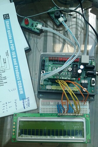
Pop-168 (ATMega 168) and LCD screen

Hi,

Okay, I've spent a good 10 hours trying to get this to work (to no avail). I have researched / Googled for many many hours - I have read 100's of forum posts and suggestions. None seem to work for me. So, now I am asking for help on this forum.

I purchased a Pop-168 ATMega168 Matchbox as a Pop-builder kit a few years ago - I moved house and it got tucked away in a cupboard until a few days ago when I re-found it! I have been using an LCD screen with a Basic Stamp 2 and it works fine.

I installed arduino-0022 and noticed that a new LiquidCrystal library has been included (I think the last time I used this it was version 007!) I thought it would be good to hook the two together. I tested the Pop-168 with some basic tests to make sure it was working okay. It flashes LEDs, plays sounds and reacts to button presses. Excellent! I successfully uploaded code and it executes okay, so I know the device itself is oky.

I took a look at: Arduino Tutorial - connecting a parallel LCD and it seemed simple enough - I just had to translate the Pins used to the ones on the Pop-168 (see schematic_01.jpg attached below).

Originally I just attempted to output text to the LCD. This only resulted in the Black boxes being displayed. I read about attaching a 10k POT, I tried that and whilst the contrast went up and down it didn't make any difference. I then read that I could just connect LCD Pin 3 to GND to get max contrast, so I opted for that to reduce dependencies.

As a test I then extended the sample code to flash an LED and play a sound so that I could confirm that the code was working okay. Here is the code I am currently using:

#include <LiquidCrystal.h>

#define LED1_PIN 2
#define SND1_PIN 3

#define RW_PIN   9
#define EN_PIN   8
#define D4_PIN   4
#define D5_PIN   5
#define D6_PIN   6
#define D7_PIN   7

LiquidCrystal myLcd(RW_PIN, EN_PIN, D4_PIN, D5_PIN, D6_PIN, D7_PIN);

void setup() {
  pinMode(LED1_PIN, OUTPUT);
  noTone(SND1_PIN);  

  myLcd.begin(16,2);
  myLcd.println("Hello World!");

  tone(SND1_PIN, 400, 200);
}

void loop() {
  digitalWrite(LED1_PIN, HIGH);
  delay(1000);

  myLcd.clear();
  myLcd.setCursor(0,0);
  myLcd.println("tony");

  digitalWrite(LED1_PIN, LOW);
  tone(SND1_PIN, 623, 400);
  delay(1000);
  noTone(SND1_PIN);
}

As you can see I have used a breadboard and attempted to make the connections as clean / tidy as possible. I set the LCD Pins 7-10 to GND just to be sure.

LCD PIN POP-168
1 GND 12
2 +5v 10
3 V0 12 (gnd)
4 RS 9
5 R/W 12 (gnd)
6 EN 8
7 D0 12 (gnd)
8 D1 12 (gnd)
9 D2 12 (gnd)
10 D3 12 (gnd)
11 D4 4
12 D5 5
13 D6 6
14 D7 7
15 + (backlight not used)
16 - (backlight not used)

As you can see in the pictures, all I am displayed is a row of Black blocks instead of the "Hello World" and "tony" text.
I tried the Serial example also, when I type some text and send it to the Pop-168 it just displays that same set of Black blocks.

I have a DC Input to the Pop-168, I also tried using a separate power supply directly to the LCD (just incase) - this made no difference.

I tried another LCD screen (same as previous one), that outputs exactly the same. I can confirm that the LCD screens are working okay and that the Pop-168 is working okay.

To me, it looks like the LCD screen is not being initialized correctly via the Library code - is this a correct assumption?

any help / guidance greatly appreciated!

thanks

tony

small_01.jpg

In your sketch you have a pin called "RW_PIN". That should be the RS (Register Strobe) signal of the LCD, not the RW (Read/Write) signal. Is it?

To me, it looks like the LCD screen is not being initialized correctly via the Library code - is this a correct assumption?

It's definitely not being initialized properly but the library code has proven to be quite reliable since it was changed in Arduino v0017. Are you sure that you are using the current library?

I hope you realize that both your board and Lady Ada's are upside down, the row of blocks you see is the top row of the display.

#define RW_PIN 9

LiquidCrystal myLcd(RW_PIN, EN_PIN, D4_PIN, D5_PIN, D6_PIN, D7_PIN);

What you have defined as RW_PIN should really be RS_PIN but since you have been consistent in using the wrong terminology this is not your problem. (It looked like John addressed this part while I was writing my reply.)

Most LCD modules have pin 1 near the outside edge of the board (as drawn on the diagram you posted), but some of the Optrex DMC series boards do indeed have pin 1 nearer to the center of the board. Since your contrast potentiometer worked when you tried it I guess that the pin orientation is not the problem either.

It looks to me like your equates are correct from what I can tell from the Pop-168 ATMega168 Matchbox schematic and your photos.

I would try a reinstallation of the Arduino IDe to make sure that everything is up do date. I would also get rid of everything in loop() while you are troubleshooting and just concentrate on getting the "Hello World" part to display.

Don

RS (Register Strobe)

RS = Register Select

johnwasser:
In your sketch you have a pin called "RW_PIN". That should be the RS (Register Strobe) signal of the LCD, not the RW (Read/Write) signal. Is it?

You are correct, it should have been RS_PIN rather than my misleading use of the label RW_PIN, on the board it is connected correctly. Must have been my fat fingers pressing W instead of S :wink:

Hmmmm...okay, well I downloaded the 00022 IDE 2 days ago, so it should be the latest.

I tried a few more things and got a bit frustrated, so I've ordered a DUEMILANOVE 328 http://www.dfrobot.com/index.php?route=product/product&path=35_38&product_id=49 - I'll give that a try with the LCD when it arrives (the board and code will match all of the existing examples).

Interesting development board. Where did you get it?

When you get your LCD working you are going to see some funny characters if you use println() since that function is not supported by the LiquidCrystal library. Also you don't need to set the cursor to 0,0 after clearing the display, that will happen automatically. Why are you continually printing your name in loop()? Stuff that isn't going to change should be in setup().

Don

floresta:
When you get your LCD working you are going to see some funny characters if you use println() since that function is not supported by the LiquidCrystal library. Also you don't need to set the cursor to 0,0 after clearing the display, that will happen automatically. Why are you continually printing your name in loop()? Stuff that isn't going to change should be in setup().

Don

Hi Don, thanks for the tips (println() and 0,0) - I'll remember that from now on.
As to printing my name in a loop, well.... that was just me trying to get something output to the LCD.
It will actually contain the output values in distance (inch/cm) from a parallax Ping))) sensor (I have this setup and working okay in a different sketch - outputs to the Serial monitor on my laptop). I want to output that data to the LCD instead of the Serial, but to reduce complexity I just inserted my name in the above code.

tony

liudr:
Interesting development board. Where did you get it?

It was a few years ago now, so I do not recall the exact place I purchased it, but it is from this supplier: http://www.inexglobal.com/products.php?type=micro&cat=AVR&model=popbuilder
It was a nice beginner kit, you get quite a few sensors to start off with. Only problem nowdays is that the layout of the pins etc.. is not the same as the 'usual' Arduino info available. That's why I've now ordered one of these: http://www.dfrobot.com/index.php?route=product/product&path=35_49&product_id=345

Another sonic ranger + LCD project! I did one a while back and got quite some attention on instructables.com since I put it on my car and used it to back my car.

code and details:

You will want a speaker and some buttons too.

The LCD Keypad Shield arrived before the new Arduino...... I thought I'd give it a try with the existing Pop-168 and using the LCD4Bit_mod library and example sketch it works perfectly okay!
I now have a working LCD screen, a working PING))), a VMusic2 / VDrive and an SDModule and an entire afternoon to myself :wink:

(thanks for the link to the car parking sensors project - looks good!)

Nice. I think the 4-bit lcd library is ancient. You should use the included library in arduino ide. The seller/designer of this shield probably should have updated their info ages ago.

The red foam might be weakly conducting so I would not rest power-on electronics on it. :wink:

liudr:
Nice. I think the 4-bit lcd library is ancient. You should use the included library in arduino ide. The seller/designer of this shield probably should have updated their info ages ago.

The red foam might be weakly conducting so I would not rest power-on electronics on it. :wink:

I've now recompiled using arduino ide LiquidCrystal library and it's still working correctly.
As a test, I reconnected the previous LCD screen to use the same pins as the new LCD screen and it still did not work (didn't even give black blocks this time). Now I have several new LCD Keypad Shields that are working I'll keep them safe (and off the red foam!)

thanks for the help & advice

Great! If you finish some projects, consider posting at the exhibition forum.