People try to use STM32CubeIDE as development system. Me too!
(obvious reasons: Arduino IDE, even VSMicro, are too slow compiling updates on a project, no support for a real debugger...).
Goal
Use STM32CubeIDE to code projects
Use a real debugger (e.g. ST-LINK V2/V3) to step through the own code developed
best case: have all code, every line of code, as source code (real Open Source), control over every single instruction (able to debug, able to fix code ... not sitting in a hidden library)
So, I have started thinking how to do.
First of all: Do not overwrite the bootloader!
Portenta H7 comes with a bootloader, needed to flash in Arduino or VSMirco your user code.
Bootloader sits in same flash ROM, from 0x08000000... 0x0803FFFF. Do not overwrite, never erase, if you are not sure, that your entire startup code works, it does all what is needed, esp. to program the PMIC chip on board (for Power Management).
The bootloader does very important stuff (PMIC config). And a regular sketch running has the user vector table on DTCM RAM (0x20000000), potentially to update the vector entries address in a RAM (otherwise vector table remains on Read-Only-flash-memory).
So Approaches
A: we keep the bootloader working (and booting our code). Our own project comes with vector table, Reset_Handler and progresses. Works fine (I have a working project with RTOS, a thread running and blinking an LED). But we have to initialize all devices our self, which we need, e.g. USB-C UART.
B: we use the "libmbed.a" file: Yes (verified) - it comes also with a vector table, a Reset_Handler. I was hoping it will initialize the mandatory stuff, e.g. USB-C UART. But it crashes. It does NOT provide the main. And it does not enter my main() (it crashes before).
C: we do ALL our self. It means: we overwrite the bootloader. So, we can only flash a new version with the connected debugger. Not possible anymore to use other IDEs, to let flash our FW via "dft_uitil.exe", no OTA ... nothing (just our debugger is left).
The "only issue": we have to do ALL and all properly for the startup, e.g. to program the PMIC, for the STM MCU power, potentially relocate the vector table to DTCM RAM etc.
So, it would be nice to use STM32CubeIDE and to program a sketch in the same way.
Or, to have all source code files available in project and full control over every single line of code.
At least: using an SWD debugger, connected on target, which let's us step through OUR code - would be very nice.
Possible, at least, approach A works for me.
The next step would be:
if I have a "bare-bone" project (which works fine already) - how to configure and use other devices, e.g. the USB-C UART?
later it will come to the issue to bring-up SD-Card, SDRAM ... our self.
best would be: we setup STM32CubeIDE to find all the H-files, to use the libmbed.a file and to do all in a similar way. How to merge files, how to define Include-Paths...
STM32CubeIDE linker script
If you want to start with your own trials, here my linker_script.ld I use (for the CM7 part, rename it into *.ld when using it: linker_script.cpp (4.9 KB)
Next Steps
extend the working (standalone CubeMX) project: add more devices needed, e.g. USB-C UART.
I am interested in part A where we do not overwrite the boot loader, that should be simple. But I cannot afford to spend time on writing a BSP. I have no problems with reusing the Arduino BSP for as much as I can, assuming it works.
My approach is to convert the Arduino build lines into an Eclipse project. This will be a generic C/C++ project with Makefiles/Cross gcc. That will give me the full browsing capability that the Arduino IDE lacks. The command line options are simply copied and pasted into a FLAGS build variable, one for C and one for C++ files. Binary code/libraries are linked in just like how Arduino builds it. Actions are implemented as make targets. Each of these targets can be exposed in the project tree as an icon, so to perform an action you can simply double-click on the icon in the IDE.
This (hopefully) includes downloading the code through ST-Link v2 and starting the debugger. About the latter I am not 100% sure if I can do that in a generic Eclipse or if I have to be in the STM32CubeIDE - but anything that has a command line equivalent can be implemented as a build target, so it should be possible IMHO.
While this will not let me build a sketch from the STM32CubeIDE, it will let me use it to test and implement MCU specific code without destroying the bootloader (assuming that your part A works for me), that I can then include in my sketch and build from Eclipse with the Arduino H7 BSP the same way that the Arduino IDE would do it. It should not take too long. I have it to the point where I can compile the files of my sketch, today I will finish the linking and see if I can use ST-Link v2. I did something like this before for an unrelated project.
Working this way specific for the tool chain versions that I have installed. Every time they are updated, I need to check if my project needs an update. Same with the Arduino build lines that I used to start from - if I add stuff it may need to change. But these are minor concerns, I think it will work for me well enough without being overly distracted by BSP development.
clock configuration works (minimal, for MCU core and USB only for now)
RTOS (CMSIS RTOS V2) is running: idle task (blinking LED) and UART task (echo USB VCP COM)
USB HS (with external PHY) is up and running: as STM VCP device (needs a driver), echo all received characters - works
Next TODO:
initialize I2C and configure PMIC chip (again, even done in bootloader)
add my devices I need (SPI, I2C) and application code (e.g. command shell and decoder), add ETH and network support (HTTP server), add SD Card and TFTP to access it
Optional: initialize memory controller for SDRAM having available (and QSPI flash device, not so important)
Meanwhile, I was able to debug the Arduino-built ELF file using the ST-Link v2 from the STM32CubeIDE. The basic idea is very simple,
Copy the first 2 "imgtool" lines from the Arduino build and edit the "buildTempDir" and "cacheTempDir" with paths where you want to keep your stuff that do not change every time. Replace all \ and \ with / and put "" around the paths that have spaces.
Run the commands from a shell (I used Cygwin, haven't tried cmd yet). It will build the ELF file and create a cache library just like the Arduino IDE would in the temp file directories, but this time in a known and fixed place.
In the STM32CubeIDE, create a debug configuration from "GDB Hardware Debugging" for the ELF file:
(a) Under Main, enter the path to the program (ELF) file, and enter a project name (I don't think it matters which one AFAICT),
(b) Under Debugger, enter the full path to the arm-none-eabi-gdb.exe file (under your Appdata such as C:\Users\xyz\AppData\Local\Arduino15\packages\STMicroelectronics\tools\xpack-arm-none-eabi-gcc\10.3.1-2.3\bin\arm-none-eabi-gdb.exe) and select ST-Link as JTAG device,
(c) Under Startup, uncheck the "Set program counter at" box.
Build the ELF file using the commands under (1). If you do not like entering commands, create some build targets with corresponding makefile.targets fragments in a C++ Makefile project so you can double-click on an icon to execute it.
Double-click the reset button to put the PortentaH7 in download mode and copy the last 2 Arduino build commands (after imgtool exit) to download the image via UDF. (I suspect there might be a command option that could eliminate this step, TBD).
Copy the ST-Link v2 connect command from the build configuration of a STM32CubeIDE project (Debugger tab -> Show command line) and run it from your shell. This will make the ST-Link v2 blink in green ready for a debugger connection. (Here again you can put this action under a makefile Build target if that's more elegant).
Click Debug in your debug configuration for the ELF file. It will now connect to the target and stop at some obscure entry point.
Click the reset button on the Portenta H7 and check in the Device manager if a COM port is created. Now click Resume (F8). Click Pause if you like, you are now debugging as usual.
This is useful for those who don't mind doing pure MCU development in the STM32CubeIDE and copy the code over to an Arduino integration project. It can all be done from within the STM32CubeIDE under a custom project that includes your Arduino integration source code.
I just got this working and hope that my summary is complete. I read some other threads where people were wondering how to debug Portenta H7 code so maybe it helps them so long as we don't have a custom BSP for it.
Next step is working:
I can build now project in STM32CubeIDE without a need to use the bootloader.
The code starts at 0x08000000 (begin of flash) - and overwrites the bootloader (I do not need any code from bootloader initialization).
When the PMIC is properly initialized (I do as earliest as I can, even before any SysClock configuration) - it boots fine (just configure I2C1 and write to PMIC registers).
The SysClock configuration was a bit tricky (some code on shared file "system_clock_override.c" does not work)
COOL.
Now I have full control over every single line of code, I can use the entire STM32H7 MCU flash storage (my FW will be large and needs also the 64KB space occupied by bootloader).
I can step from the very first instruction, e.g. in Reset_Handler(), in startup.s - with external ST-LINK debugger (which is needed).
The only "side effect": I can only flash with external SWD Debugger (ST-LINK) connected. Fine for me, but later when I want to let my friends update their boards with a new version of FW - not so easy anymore (they need external debugger as well - board does not have an onboard debugger).
Never mind: the basic project works with and even without bootloader (just change linker_script.ld where your "user code" is located: 0x08040000 vs. 0x08000000).
And I can power cycle the board - without to get the orange LED and it comes up properly (my USB VCP UART is alive, my heartbeat LED is OK ...).
BTW:
when I have check the I2C to PMIC with an oscilloscope - the original waveform looks really odd (not a nice duty cycle). My PMIC I2C looks better.
And I hope, the board will be more reliable with my project (and board not bricked anymore so easily).
In the process, did you face any issue with the clock config?
Someone has started a port of the Portenta H7 for the Zephyr RTOS and he cannot get the clock running at more than 100 MHz on the M7.
I have tried myself and even with specifying other prescalers values, the system is still running at 100 MHz while the system thinks it is running at 480 MHz (UART corrupted and blink sketch 4,8 times too slow).
I know that the Zephyr code is very different but just in case we have missed something at the init step.
Delicate question: There are some HW issues to bear in mind:
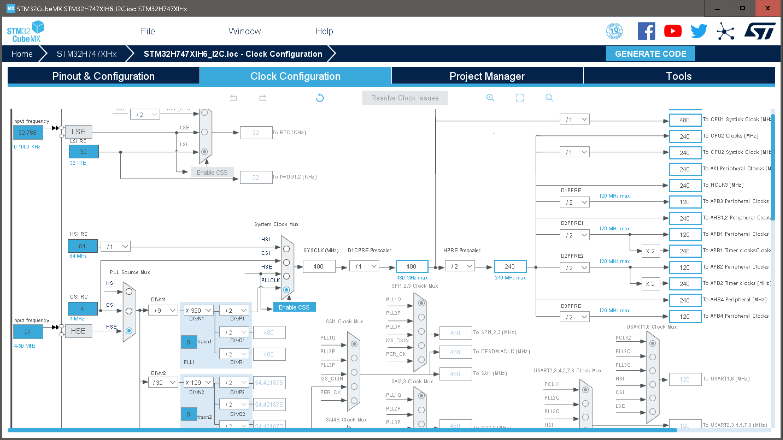
there is an external clock oscillator (you need set to use "bypass" in MCU), 27 MHz, not 8 MHz as on many other boards. If your XTAL frequency is "assumed" wrong, the MCU core clock is wrong.
Also: for the XTAL to work - there is an enable signal OSCEN (PH1_OSCOUT). So, the MCU runs first on internal HSI clock. And this PH1_OSCOUT must be configured as GPIO output and driven by MCU in order to enable the external HSE, before it can change from HSI to HSE. (Usually, this PH1_OSCOUT is left open when "bypass" and external clock is used. But here it must be a driven output).
I could imagine, your system runs still on HSI clock - which is 64 MHz and does not use any PLL. The PLLs can be used only on HSE. And the clock protection unit MCU (CSS) might see that external clock is missing and falls back to HSI. So, I would check first if PH1_OSCOUT is configured and driven to enable external clock generator.
When this enable signal is there, the 27 MHz running (nothing to see), you can change to HSE and PLLCLK. Now, when you play with the PLL config - you would see an effect (different clock speed).
A good help to understand and to play with clock config is to create a project in STM32CubeMX.
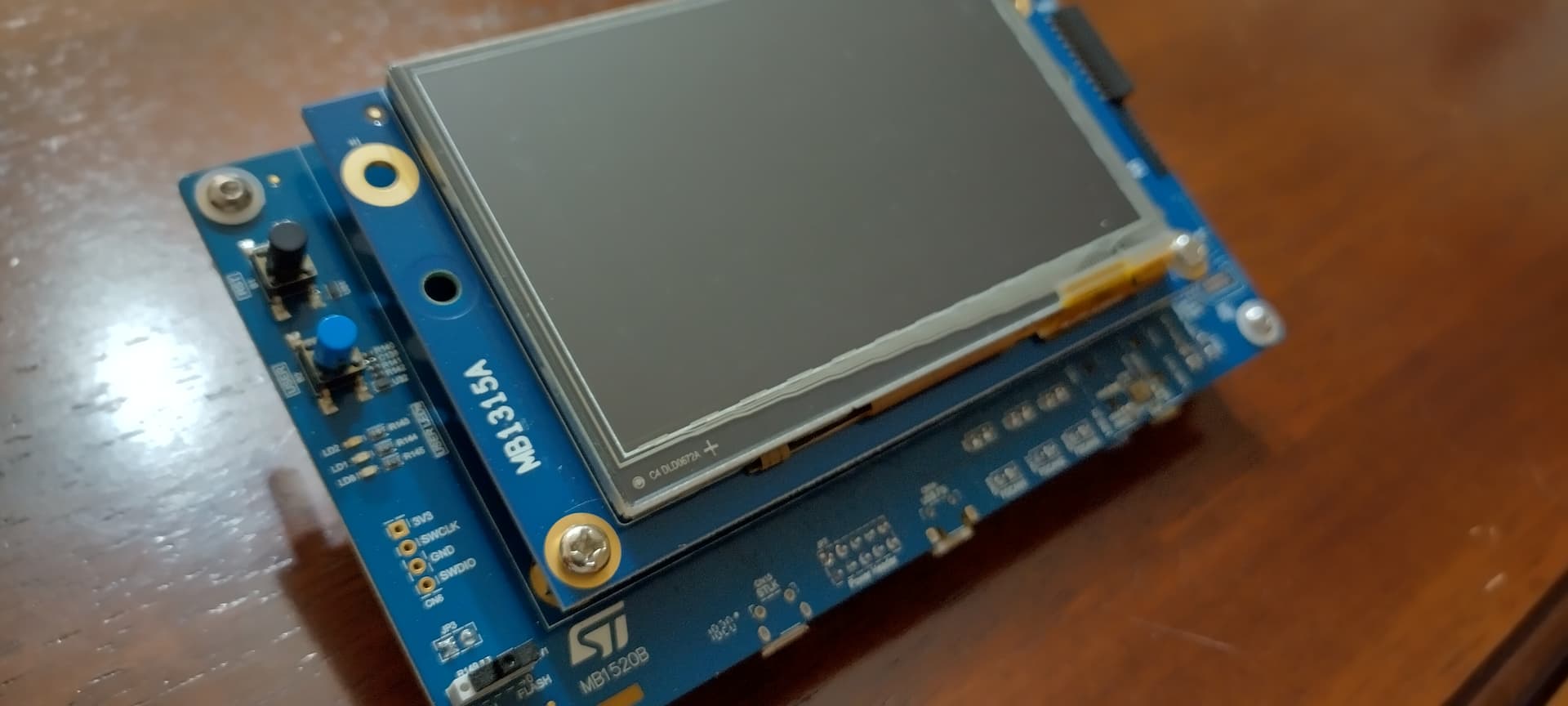
I don't have a Portenta but I do have this directly from ST. It's based on the same STM32H7 MCU. I mostly write baremetal code (bypassing ST's own HAL)
FYI,
may project is progressing: meanwhile I have ETH and HTTPD demon running on "bare metal" Portenta H7: it was tricky, because LwIP, a newer version, uses rand() and it has crashed all the time (it uses malloc() and needs a .heap).
OSCEN should be driven high, in order to enable the onboard OSC chip.
Sure, any other STM NUCLEO board can be programmed, not related to Portenta H7. We cannot compare Portenta H7 with any other STM board: it is very special, e.g. the PMIC config, the schematics etc.
The Portenta H7 is not directly supported by STM: you will not find any BSP. And Arduino does not provide a BSP. The only option is to use this board with mbed/Arduino, but not as bare metal.
Even I could make progress to code all (as really Open Source) myself, every single line available as source code - this board is pretty tricky (due to PMIC, schematics). But it works.
Just: you cannot assume it is an STM board and to find BSP and sample code for bare metal programming. It is an Arduino board and intended to be used with Arduino IDE and ARM mbed API.
I have been re-reading your first post with the three options. You mentioned in option (B) that libmbed.a does not provide main. If you build the Arduino way you will get a main (I presume Arduino provides that, I could check). In that case of course you can't have your own main, your code will need to be called from setup() and loop() that are called from Arduino's main(). That same main() activates the serial over USB (I presume that's the same as the USB-C UART). But, in the debugger, you have to press the reset button (twice) to have it do this. The debugger first takes me to Reset_Handler(). When I press Run it hangs in main() in the serial over USB port creation until I hit the reset button two times, then I can get into my setup() and loop() implementations.
Regarding your SWD requirements, this can be done through a simple makefile project as I described earlier above. This project can live in the STM32CubeIDE, in fact it offers the MCU-ARM-GCC that is helpful because it adds some include paths and macros to the project. Then you can use SWD to step through your own code. With some more work you can also step through the generated code and the HAL drivers, but why because that is typically used for STM-generated code that will need no debugging just options testing. I feel no need for that.
There are a few more details that I discovered later, namely use .bat files (called from the makefile) for downloading the code and launching the ST-LINK GDB server because for some reason a Windows environment helps. Altogether it works OK for me, and it did not take too much work. I may document that later in a separate thread.
You said that Arduino does not provide a BSP; I would argue that it does. The boot loader configures the PMIC, the main() configures the serial port, interrupts are supported based on mbed OS (from looking at the stack traces), and it supports saving the executable in ROM so it is launched when starting the board. To me that is quite a bit, then there are examples about how to program the external SDRAM and flash.
About the clock, I tried programming that to speed my board up and got nowhere. Eventually it turned out that if I just commented the STM32-generated clock configuration code, I got the speed that I wanted. So, Arduino must be setting it up to my liking, had I known that it would have saved a day of work. The STM32CubeIDE was not very helpful; I spent half a day looking for options that should be there and I could not find them. Understanding the clock configuration would take me a week so I'm glad I don't have to.
Sure, a BSP is there - but I want to have it as (Open) Source code (all under my control).
Sure, there is a main(), and the code generated by Arduino IDE provides the call of setup() and loop(). But I want to use and provide everything myself.
External debugger and twice reset: obvious: the bootloader is entered, which enters my sketch. Sure, I can debug from there on. But I want to debug from the very first instruction, e.g. Reset_Handler(), even the one in the bootloader (all as Open Source).
Never mind:
My bare metal Portenta H7 is working, I have PMIC, USB-C UART, ETH network running, all as source code from very first line (and even possible to overwrite the bootloader and use the space in flash).
I am fine (and no need to understand who Arduino sketch works - which I know). I want to get rid of Arduino IDE, sketch, bootloader anyway - and I have it.
Remarks:
It is standalone project - as C-code. No Arduino code, no LIB - all as source code.
It is a project which needs external debugger to flash the code! It overwrites the bootloader on Portenta H7 boards (and uses the entire flash space). The bootloader is gone!
It has these features:
initialize the PMIC on board
initialize and start RTOS (CMSIS OS ver. 2). Just the CM7 is running - the CM4 is not used and not released
USB-C CDC UART (VCP UART): with a command shell and command decoder (see "help" on UART terminal)
it initializes ETH and runs a TCP server (port 80): with a web page, Web Browser mode and binary commands via TCP - for a Python script firing commands via network.
Python script: Python script for ETH Portenta H7 commands
initialize SPI with clock config, use Portenta H7 as a Network SPI Adapter (from Python script),
the SPI runs in DMA mode - much better seamless SCLK (not byte bursts as Arduino API does)
use RTC BKPxx registers to store system config values which are not reset, not overwritten with a system reset (but volatile with power cycle)
Have fun with the project.
You might be able to modify a bit and use the Arduino bootloader: "just" modify the linker script (to build for start address 0x08004000) but check that Vector Table is relocated to DTCM RAM (0x20000000) and Vector Table is copied from flash to this location.
User I2C added (available as UART commands - not yet/TODO as Python Network request). It works to read/write the onboard PMIC (ATT: fix PMIC slave address for now). And it has an i2cclk selection (0, 1, 2) for 100, 400, 1000 MHz. The PMIC is configured now using 1 MHz I2C clock (faster boot time).
My next TODO list:
add I2C binary read/write to network commands (for Python script)
extend the syscfg - the parameters to survive a system reset, reconfigure the system after reset with modified syscfg parameters (modify syscfg and do fwreset to restart system with modified config, e.g. SPI modes, timing parameters ...)
maybe: add SDRAM, SD Card (and TFTP), QSPI flash on board (but very low prio)
maybe: release the CM4 and let it do something (no idea what it can do?)
Everything available right now seems to work fine. Cool.
And it seems to me: my board is much more stable (has never really bricked again).
And the great benefit:
now I can see any line of code, all as real Open Source, I can use debugger to step through the code (on any code line) ...
My goal achieved: I want to have a project with full control over every single bit (source code, features, MCU optimization, HW features to use in the "right way" - Arduino does not do! SPI LSB first config not possible, no SPI DMA, all as SW SPI with SCLK coming in byte bursts - I do not want to have it this way ...)
I am happy being able to keep going without the Arduino stuff.
And: the CubeIDE is much faster. And it works now in office (Arduino - I cannot use in office - it takes days to compile).
So, I think I will finish here (for this thread, but I keep going to extend this project).
It works to have my own full Open Source project, without Arduino and full control on everything.
BTW: this project uses some "tricks" to optimize for speed, e.g.:
configure MPU for cached and non-cached regions (anyway necessary to do for ETH Network)
use DTCM RAM for stack and heap, used by RTOS for all local stack data
use ITCM RAM for code: place most often used functions into ITCM, INT Handlers
use SPI in DMA mode, with Cache Maintenance functions needed
And, as mentioned: I use RTC BKPxx registers to "save" syscfg parameters which will survive a system reset (e.g. via command "fwreset", used to start over on MCU like reset from command line command).
The project is not really "tricky" but I use some "tricks" in combination, e.g. the Linker Script and startup code, attribute to place code on specific memory locations (ITCM, DTCM) ...
A project for people knowing CM7 and STM MCU quite well, with the intention of fastest performance possible.
Have fun ...
MISSION ACCOMPLISHED !
Why Arduino team cannot do and is not willing to provide similar project/solution/IDE - all as real Open Source ...? Use my project as a kind of Open Source BSP (even I do not have (yet) a real BSP file) - for CubeIDE (or any other IDE).
FYI,
Now I have also SDRAM and SDCard working.
SDRAM just with a "test" command (to verify if entire SDRAM and any bit can be written).
SDCard for "script" files, to print, execute files from card etc. (see via command "help" on UART).
Also TFTP is working now - to transfer files to/from SDCard via TFTP network command.
you have to write to Flash start address 0x08000000:
ATTENTION: it will overwrite, rip out, the Arduino bootloader
in order to flash the BIN file directly - use an external debugger connected or the BOOT1 (BOOT DIP switch) bootloader option for "dft-util.exe" (flashing via the STM bootloader, not the Arduino bootloader)
When using SDCard:
It needs to enter a command "sdinit 1" first, before you can use SDCard and even to access SDCard via TFTP it is needed. SDCard is not enabled per default (it needs the command).
Well done @tjaekel
You have accomplished a lot of work to get this full open-source project.
For now, I will try to keep the Arduino system to be able to use the existing libraries.
But I agree that there is a lot of trade-off. So for the ADC, I need a low latency so I have used the ST HAL directly.
I would like to have Zephyr-RTOS working on it to try this OS and their drivers. But for now, we did not managed to change the clock frequency and are stuck at 100 MHz.