Check the datasheet, the STM32 family usually has alternating pins, usually you have to perform a command to activate the secondary function of the pin.
No idea why read blinking LED (which is a Hardware_Fault).
But the signals you want to use are already in use:
PC10 = SDC1_D2
PC11 = SDC1_D3
PC12 = SDC1_CK
It seems to conflict with SD card. Even the Hardfault_Handler called is "strange": you might drive for sure against SD card or you would apply signals to SD card (and get an unexpected response from it).
An example configuration source can be the STM32 IDE (STM32CubeIDE), I have been using this IDE and I find it easier to use this configuration method than to use the Arduino IDE for more complex projects, even so you can see which resistors are being modified.
3 Alternate function mapping to pins
In order to easily explore the peripheral alternate functions mapping to the pins it is
recommended to use the STM32CubeMX tool available on http://www.st.com.
Sure, there are additional SPIs, but I meant: "check the schematics - the pins are already in use".
It does not make sense to see SPI pins in datasheet when they are already connected and in use:
they are not free anymore to be used as signals based on datasheet. The board schematic limits the usability.
It does not matter - if these pins are connected already on board, used for other purposes, a driver configuring the same pins but for other functions.
If you change pin ALT function - you do not change the schematic!
You can have a driver conflict, you can get a signal which is driven already by a component on board.
The SCHEMATICS matters first - if and what is possible!
My concern is to understand the board I am using.
If I would design my own board - you are right: it is your choice and knowledge. But if you get a board and w/o any clue how pins are already used - trying to use pins just with datasheet creates potentially just risks, damages and strange behavior.
My message was: understand the schematics of the use board first before you try to use signals (which are already in use and fix in purpose).
Yes, possible to use pins which are free!
If he would check for other pins, for other SPI signal "potentially" possible, but at the end used on board (schematics) - no chance.
So, I would argue: if Portenta H7 pinout does NOT tell you these signals are possible "as" or "free" - do not try to use pins not mentioned (and already in use).
Even you know there is another SPI possible (datasheet), but you do not see the Pins free on pinout - they are NOT free.
Try to use only pins and signals which are mentioned by the Portenta pinout as "free user pins". Assume: all other MCU pins (not mentioned) are already in use (internally, on board, never mind what MCU datasheet would "allow" - it is not allowed by board schematics).
Unfortunately Arduino boards are made this way (P.S.: It doesn't look for full use of the microcontroller, it just looks for a basic user usage), maybe STM32 boards are more flexible in this matter.
I had posted incorrect information. My apologies.
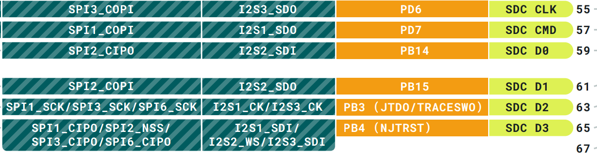
The pins I want to use are PB_4, PD_6, and PB_3 SPI3.
These also conflict with SDCard, but SDCard has Pin setting in .arduino15/packages/arduino/hardware/mbed_portenta/3.1.1/libraries/Portenta_SDCARD/src/BSP.c, so and I think it is in a FREE state without this.
I did some research and wrote the following code. But it still doesn't work.
I get an error when getting the SPI instance in spi.begin().
I am also looking for a second SPI - very confusing:
breakout board silk screen has "SPI0" - which does not exist in MCU: it is SPI2,
and "SPI1" does not seem to be connected (the J2 high density header does not forward, as "RSVD").
SPI3 with these signal could actually work - if SD card is not used/not initialized. I do not know if mbed/Arduino code checks the pin mapping and "prohibits" to use pins already associated with other functions:
But not all PWMx come out on JDIGITAL header, but potentially on breakout board PWM.
SPI1, SPI3 and SPI6 are not usable: they have often signals used for USB, SD RAM, ETH controller.
BTW: have you checked if these signals are available as GPIO?:
Configure each of these signals as GPIO output, drive a 0 or 1 and see if the board pin toggles.
If this works - all these signals are available and can be driven - if it still fails to configure as SPI (with a different ALT mode), I could imagine this:
mbed/Arduino API does not allow to configure pins for other ALT functions when the pin mapping sees they are already used for other purposes
you have still the option to use the HAL drivers directly, configure and use the SPI with regular C-API of STM HAL drivers
I could imagine that C++ mbed/Arduino API does not allow to "hijack" pins and signals.
I found a solution.
Actual pin definitions are in PeripheralPins.c. For example, PB_3_ALT0 is defined as GPIO_AF6_SPI3 in this line.
I can use SPI3 by using PB_4_ALT0, PD_6, PB_3_ALT0 pins
Oh, cool! Well done.
So, it is MCU SPI3 .
It matches with my pin mapping: PB4 = MISO, PD6 = MOSI, PB3 = SCLK (PA15 or PA4 would be NSS for HW controlled NSS).
Where to you grab the signals (on breakout board)? It should be spread over different silk screen pins. Where to find all these signals?
Anyway - well done.
(but why Arduino does call it PB_3_ALT0 when it is actually AF6 in datasheet? Oh men, this board and esp. Arduino SW drives me crazy - found another issue with MCU XTAL and core clock...).