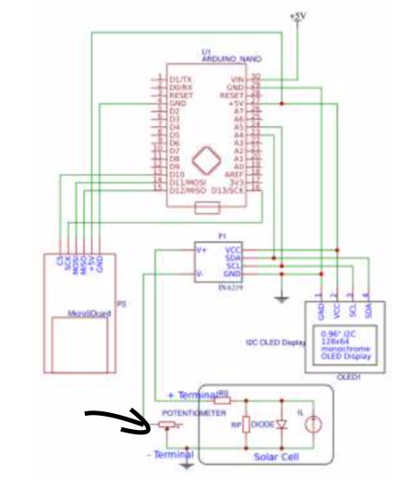
I want to copy the following circuit I found in a paper. It is used to measure the V-I characteristics of a solar cell. A potentiometer is used to change the resistive load and at each point current and voltage is measured.
In the paper it says a potentiometer with "sufficient power rating" was used. The cell I want to use will have around 5W peak. If I check for Arduino potentiometers I find most power ratings at 0.25-0.5W.
Am I looking for the wrong component and the thing should be called something different or do I need to find another solution to the problem?
"Am I looking for the wrong component and the thing should be called something different or do I need to find another solution to the problem?"
5 watts is not a lot. If you need a variable resistance load, what you may be looking for might be a rheostat that is capable of dissipating heat. What I would do is use the wire in something like a small electric heater or hair drier (unplugged!) to provide the resistance. Connect along the wire in different places with a jumper wire to vary the load
I don't see what the pot is doing. The attachment is a little fuzzy. It looks like it goes between the A/D(?) negative input to ground. Assuming the V- of what I think is an A/D it will be high impedance and no current will flow through the pot.
@JohnRob
The +output of the cell goes through the 0.1 ohm shunt resistor of the INA229 current/voltage A/D,
before being loaded by the pot.
A wirewound pot of the right resistance is not easy to find, and could be expensive.
A power transistor on a small heatsink with it's base current controlled by a common pot could be easier.
Leo..
The +output of the cell goes through the 0.1 ohm shunt resistor of the INA229 current/voltage A/D,
before being loaded by the pot.
Sorry I couldn't read the number on the schematic. From what I can tell, the INA229 does not have an internal 0.1 Ohm shunt. At least I think it doesn't, I could not find a datasheet on the INA229, but the INA233 does not have a shunt.
Regarding the variable resistor ( old days would be a Rheostat, mostly used in non electronic power circuits)
So:
Determine the highest voltage the cell can provide.
Identify the lowest current reading you wish to measure (excluding 0 current)
Ideal Rheostat value will be R = Vcell/LowCurrent.
Pick the next higher "standard" value
power capability should be ~ 10 watts (5 Watts of the cell + derating so you don't risk overheating the Rheostat.
Having said that, I would consider purchasing a bunch of different value 5W resistors and connect them such that you get the current points you wish to measure. You could probably get by with 1W or 2W resistors since most likely you will have at least a couple of resistors in series.
Wawa's suggestion sounds cool but I think you might end up spending more time playing with he pot controlled transistor than measuring your photo cell.
JohnRob:
From what I can tell, the INA229 does not have an internal 0.1 Ohm shunt. At least I think it doesn't, I could not find a datasheet on the INA229, but the INA233 does not have a shunt.
True, but most use this chip on a breakout board, which usually has a 0.1ohm shunt.
Leo..
JohnRob:
Wawa's suggestion sounds cool but I think you might end up spending more time playing with he pot controlled transistor than measuring your photo cell.
Why do you think so? I have never really built something like that but using an opamp to drive the gate of a power MOSFET to get desired voltage over the current sense resistor should work well. Using fixed resistor would need much more effort if more than a very few points is needed.
Yes many many times, however the original suggestion was to use a pot driving a transistor and as you know as the transistor heats up current gain goes up making it difficult to control open loop.
I don't really know but my guess is the OP is not looking to build another circuit to perform their test. However if they do, your suggestion is spot on.