So defining 4 IO-pins for the relays as outputs
and initialising the 4 timers looks like this
void setup () {
  for (byte Index = 0; Index < 4; Index++) {
    pinMode (relayPin[Index], OUTPUT);
    RelayTimer[Index] = millis();
  }
}  // end of setup
reading in the potentiometers looks like this
void readPotentiometers() {

  // count variable Idxx from 0 to 3   (3 < 4)
  for (byte Idx = 0; Idx < 4; Idx++) {
    RELAYinterval[Idx] = analogRead(potPin[Idx]);
  }
}
checking if it is time to toggle a relay looks like this with a helper-function for the non-blocking timing
void checkRelayTimers_and_toggle() {
  // count variable Index from 0 to 3   (3 < 4)
  for (byte Index = 0; Index < 4; Index++) {
    if ( TimePeriodIsOver(RelayTimer[Index],RELAYinterval[Index]) ) {
      digitalWrite(relayPin[Index], !digitalRead(relayPin[Index]) );
      // the attentionmark!   is the NOT-operator:    not HIGH = LOW   not LOW = HIGH
      // the not-operator inverts the state              !HIGH = LOW      !LOW = HIGH
    }
  }
/* same as if you would code

    if ( TimePeriodIsOver(RelayTimer[0],RELAYinterval[0]) ) {
      digitalWrite(relayPin[0], !digitalRead(relayPin[0]) );

    if ( TimePeriodIsOver(RelayTimer[1],RELAYinterval[1]) ) {
      digitalWrite(relayPin[0], !digitalRead(relayPin[1]) );

    if ( TimePeriodIsOver(RelayTimer[2],RELAYinterval[2]) ) {
      digitalWrite(relayPin[2], !digitalRead(relayPin[2]) );

    if ( TimePeriodIsOver(RelayTimer[3],RELAYinterval[3]) ) {
      digitalWrite(relayPin[3], !digitalRead(relayPin[3]) );

only difference is the number in the brackets "[]"
*/
}
// Which pins are connected to which RELAY
/*
const byte RELAY01 = 2;
const byte RELAY02 = 3;
const byte RELAY03 = 4;
const byte RELAY04 = 5;
*/
// replaced with an array
const byte relayPin[4] = {2, 3, 4, 5};
// relayPin[0] contains value 2
// relayPin[1] contains value 3
// relayPin[2] contains value 4
// relayPin[3] contains value 5


const byte potPin[4] = {A0,A1,A2,A3};


// Time periods of blinks in milliseconds.
/*
const unsigned long RELAY01interval = analogRead(A0);
const unsigned long RELAY02interval = analogRead(A1);
const unsigned long RELAY03interval = analogRead(A2);
const unsigned long RELAY04interval = analogRead(A3);
*/

// replaced by an array
unsigned long RELAYinterval[4];


// Variable holding the timer value so far. One for each "Timer"
/*
unsigned long RELAY01timer;
unsigned long RELAY02timer;
unsigned long RELAY03timer;
unsigned long RELAY04timer;
*/
// replaced by an array
unsigned long RelayTimer[4];
// RelayTimer[0] contains value for timer 1
// RelayTimer[1] contains value for timer 2
// RelayTimer[2] contains value for timer 3
// RelayTimer[3] contains value for timer 4


void setup () {
  for (byte Index = 0; Index < 4; Index++) {
    pinMode (relayPin[Index], OUTPUT);
    RelayTimer[Index] = millis();
  }
}  // end of setup


void readPotentiometers() {

  // count variable Idxx from 0 to 3   (3 < 4)
  for (byte Idx = 0; Idx < 4; Idx++) {
    RELAYinterval[Idx] = analogRead(potPin[Idx]);
  }
}


void checkRelayTimers_and_toggle() {
  // count variable Index from 0 to 3   (3 < 4)
  for (byte Index = 0; Index < 4; Index++) {
    // check if more milliseconds have passed by as value in variable RELAYinterval[Index]
    if ( TimePeriodIsOver(RelayTimer[Index],RELAYinterval[Index]) ) {
      // if REALLY more milliseconds HAVE passed by
      digitalWrite(relayPin[Index], !digitalRead(relayPin[Index]) );
      // the attentionmark!   is the NOT-operator:    not HIGH = LOW   not LOW = HIGH
      // the not-operator inverts the state              !HIGH = LOW      !LOW = HIGH
    }
  }
/* same as if you would code

    if ( TimePeriodIsOver(RelayTimer[0],RELAYinterval[0]) ) {
      digitalWrite(relayPin[0], !digitalRead(relayPin[0]);

    if ( TimePeriodIsOver(RelayTimer[1],RELAYinterval[1]) ) {
      digitalWrite(relayPin[0], !digitalRead(relayPin[1]);

    if ( TimePeriodIsOver(RelayTimer[2],RELAYinterval[2]) ) {
      digitalWrite(relayPin[2], !digitalRead(relayPin[2]);

    if ( TimePeriodIsOver(RelayTimer[3],RELAYinterval[3]) ) {
      digitalWrite(relayPin[3], !digitalRead(relayPin[3]);

only difference is the number in the brackets "[]"
*/

}

void loop (){
  readPotentiometers();

  checkRelayTimers_and_toggle();
}  // end of loop

// easy to use helper-function for non-blocking timing
boolean TimePeriodIsOver (unsigned long &startOfPeriod, unsigned long TimePeriod) {
  unsigned long currentMillis  = millis();
  if ( currentMillis - startOfPeriod >= TimePeriod ) {
    // more time than TimePeriod has elapsed since last time if-condition was true
    startOfPeriod = currentMillis; // a new period starts right here so set new starttime
    return true;
  }
  else return false;            // actual TimePeriod is NOT yet over
}
The same sketch but without your outcommented code
const byte relayPin[4] = {2, 3, 4, 5};
const byte potPin[4]   = {A0,A1,A2,A3};

unsigned long RELAYinterval[4];
unsigned long RelayTimer[4];


void setup () {
  for (byte Index = 0; Index < 4; Index++) {
    pinMode (relayPin[Index], OUTPUT);
    RelayTimer[Index] = millis();
  }
}  // end of setup


void readPotentiometers() {
  // count variable Idx from 0 to 3   (3 < 4)
  for (byte Idx = 0; Idx < 4; Idx++) {
    RELAYinterval[Idx] = analogRead(potPin[Idx]);
  }
}


void checkRelayTimers_and_toggle() {
  // count variable Index from 0 to 3   (3 < 4)
  for (byte Index = 0; Index < 4; Index++) {
    // check if more milliseconds have passed by as value in variable RELAYinterval[Index]
    if ( TimePeriodIsOver(RelayTimer[Index],RELAYinterval[Index]) ) {
      // if REALLY more milliseconds HAVE passed by
      digitalWrite(relayPin[Index], !digitalRead(relayPin[Index]) );
      // the attentionmark!   is the NOT-operator:    not HIGH = LOW   not LOW = HIGH
      // the not-operator inverts the state              !HIGH = LOW      !LOW = HIGH
    }
  }
}


void loop (){
  readPotentiometers();

  checkRelayTimers_and_toggle();
}  // end of loop


// easy to use helper-function for non-blocking timing
boolean TimePeriodIsOver (unsigned long &startOfPeriod, unsigned long TimePeriod) {
  unsigned long currentMillis  = millis();
  if ( currentMillis - startOfPeriod >= TimePeriod ) {
    // more time than TimePeriod has elapsed since last time if-condition was true
    startOfPeriod = currentMillis; // a new period starts right here so set new starttime
    return true;
  }
  else return false;            // actual TimePeriod is NOT yet over
}
both are good usable. The difference is:
higher resistance = more sensitive to electromagnetic noise.
But both values 20 k and 100k are in a range that - as long as you don't do plasma-cutting with HF-ignition - it will work good.
The value could go down to 1 kOhm. Which means current would be 5V / 1000 Ohm = 5 mA
The map-function works like a linear function y = mx + b
But not with parameters "m" and "b" the parameters are
lowest "x", highest "x"
and
lowest "y" highest "y"
with generalised words
myY = map (myX, fromLow, fromHigh, toLow, toHigh);
To make it more clear I define another array
unsigned int PotiValue[4];
Potentiometer-values vary from 0 to 1023
and this shall be transformed into values 300 to 3000
So the code with the map-function looks like this
const byte relayPin[4] = {2, 3, 4, 5};
const byte potPin[4]   = {A0,A1,A2,A3};

unsigned int PotiValue[4];

unsigned long RELAYinterval[4];
unsigned long RelayTimer[4];


void setup () {
  for (byte Index = 0; Index < 4; Index++) {
    pinMode (relayPin[Index], OUTPUT);
    RelayTimer[Index] = millis();
  }
}  // end of setup


void readPotentiometers() {
  // count variable Idx from 0 to 3   (3 < 4)
  for (byte Idx = 0; Idx < 4; Idx++) {
    PotiValue[Idx]= analogRead(potPin[Idx]);
    RELAYinterval[Idx] = map(PotiValue[Idx],0,1023,300,3000);
  }
}


void checkRelayTimers_and_toggle() {
  // count variable Index from 0 to 3   (3 < 4)
  for (byte Index = 0; Index < 4; Index++) {
    // check if more milliseconds have passed by as value in variable RELAYinterval[Index]
    if ( TimePeriodIsOver(RelayTimer[Index],RELAYinterval[Index]) ) {
      // if REALLY more milliseconds HAVE passed by
      digitalWrite(relayPin[Index], !digitalRead(relayPin[Index]) );
      // the attentionmark!   is the NOT-operator:    not HIGH = LOW   not LOW = HIGH
      // the not-operator inverts the state              !HIGH = LOW      !LOW = HIGH
    }
  }
}


void loop (){
  readPotentiometers();

  checkRelayTimers_and_toggle();
}  // end of loop


// easy to use helper-function for non-blocking timing
boolean TimePeriodIsOver (unsigned long &startOfPeriod, unsigned long TimePeriod) {
  unsigned long currentMillis  = millis();
  if ( currentMillis - startOfPeriod >= TimePeriod ) {
    // more time than TimePeriod has elapsed since last time if-condition was true
    startOfPeriod = currentMillis; // a new period starts right here so set new starttime
    return true;
  }
  else return false;            // actual TimePeriod is NOT yet over
}
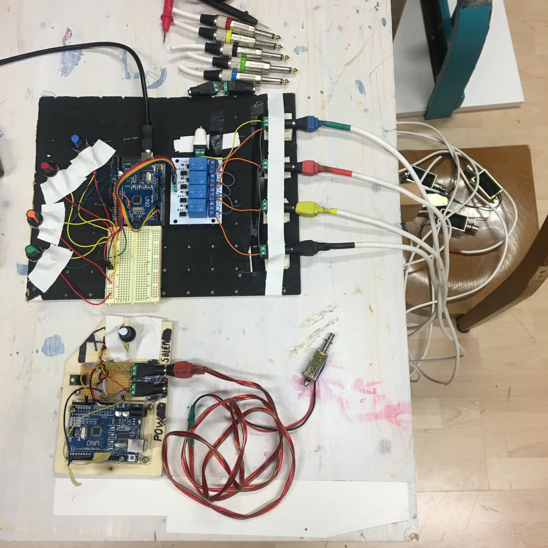
excellent, I am trying to figure out now how to make the the potentiometer only controlling the OFF state. While I am controlling 4 solenoids with the relays, and the ON state is fixed to as in a hammer fashion
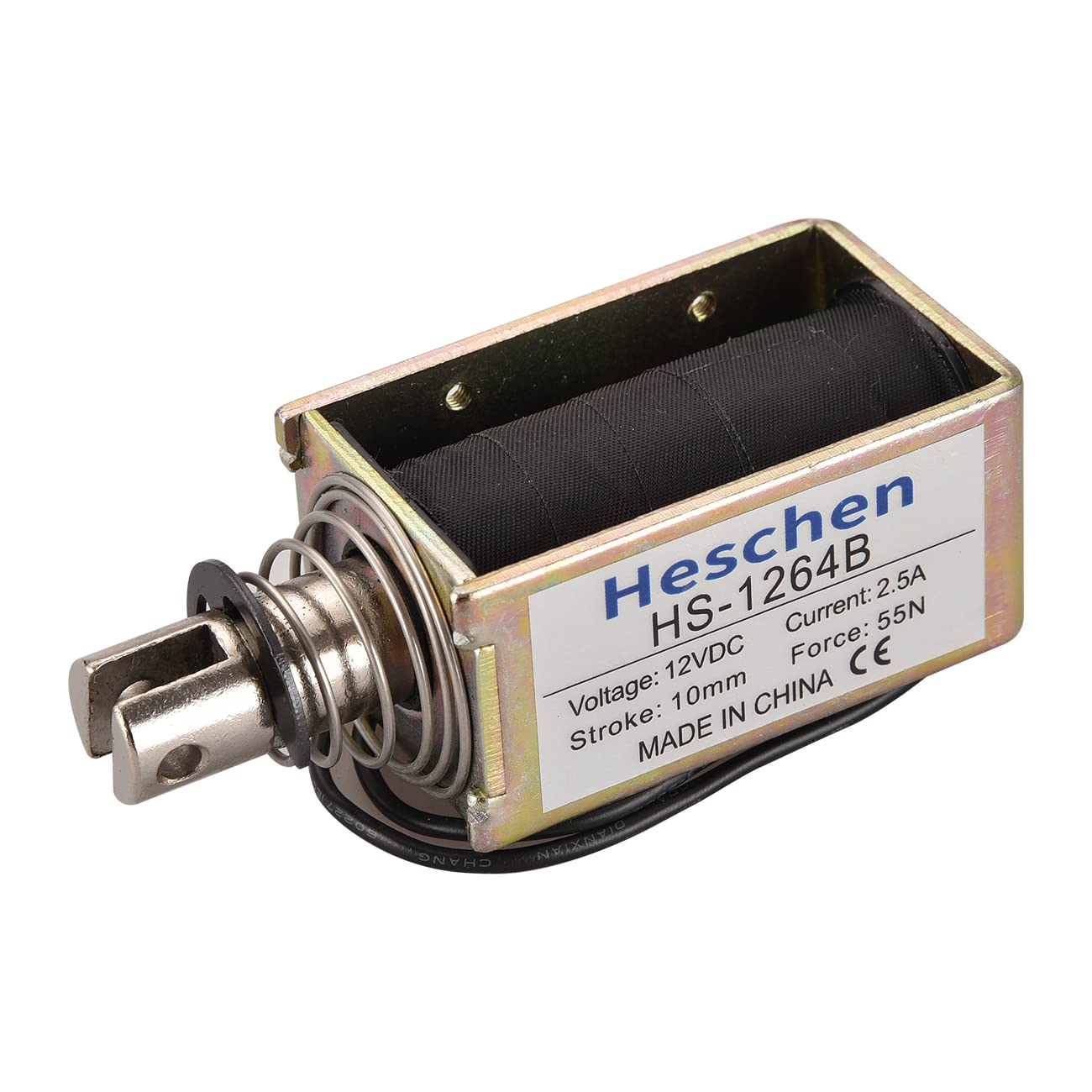
These are the solenoids in question
toggling on/off with the same interval is different than different times for on and off
you can't just toggle anymore for having that functionality.
post a timing-diagramm that gives an example how the different on/off-times look like
And then you should write your own attempt how to code this.
This attempt can have bugs or even not compile. But you should start learning programming.
And this is not by presenting ready to use code but by own attempts and asking specific questions
best regards Stefan
Hi @paulpaulson
I am designing something like this but not exactly.
It is something simple ...to have 4 solenoids drumming at different rates and controlling these rates in real time with the potentiometer knobs
thanks for the advise and your time Stefan, sadly I have been attempting to learn to code without effort for years now. This doesn't discourage me from continuing to come up with new DIY gadgets to make sound. Unfortunately I have to continue asking specialists about technical programming issues and such .
Regarding the code for the 4 solenoids, I have the code that I use on another system that only uses one solenoid and it looks like this: (the thing get complicated when there are 4 solenoids at the same time)
int mosfetPin = 2;  // the Arduino pin, which connects to the IN pin of mosfet
int potPin = A0;  // Analog pin connects to knob
int potVal = 0;


void setup() {
  // initialize digital pin as an output.
  Serial.begin(9600);
  pinMode(mosfetPin, OUTPUT);
}

// the loop function runs over and over again forever
void loop() {

  potVal = analogRead(potPin);
  Serial.println(potVal);
  digitalWrite(mosfetPin, HIGH);
  delay(100);
  digitalWrite(mosfetPin, LOW);
  delay(potVal);
}```
In general - Arrays and structs are your friends.
Don't duplicate code in your sketch. Write code once - use it multiple times.
You should not use magic numbers. The I/O pins love to have a functional name.
Do you have experience with programming in C++?
The task can easily be realised with an object.
A structured array contains all information, such as pin addresses for the I/O devices, as well as the information for the timing.
A single service takes care of this information and initiates the intended action.
The structured array makes the sketch scalable until all I/O pins are used up without having to adapt the code for the service.
It is cool stuff, isn´t it?
The code that you have posted in post #31 uses blocking timing based on delay().
If more than one thing shall happen in parallel you need non-blocking timing.
Sadly there is this always the same not explaining much too short hint to a hard to understand example-code blink-without understand ehm sorry blink without delay
So I want to encourage you to make another attempt to understand non-blocking timing
where the explanation is based on a everyday-example of pizza-baking
and uses easy to follow specific numbers like
13:05 - 13:06 = 1 minute etc.
I thought it had been clear that the concepts of blocking and not blocking were understood both since my original post (and by the way, if it's true, there are many examples on the internet that use culinary metaphors. I'm already getting hungry). The example of the system using delay was presented to generate a picture of how the solenoids are required to behave (the fact that the ON time is fixed, and only the OFF time is controlled with the pots).
I have been trying to learn to program for years without success (instead of effort, I made a translation error). It must be something at my cognitive limits. I posted my problem with faith that someone who has a better understanding of the Arduino programming language and some time to help will help me with the code. Thanks to everyone who enthusiastically responds on this forum.
Sometimes, because it looks like the boat will float, and then...
Seriously, though, I backed away from this thread not because you didn't deserve help, but because we have a habit on this forum of help-swarming posters; by that I mean, instead of letting 1, 2, or 3 helpers try and move the OP forward, we get a dozen or more all pulling in different directions, and no one tries to think about this from the OP's viewpoint. This thread is a classic, with several approaches and several solutions from some excellent helpers, stomping all over each other. Hilarious, if you just sit back and watch, but it must have been frustrating for you.