Hi, i'm making an automatic plant watering system, as the project has grown the mess of wires got annoying so i decided to tidy things up a bit by making a socket board for the power connections needed for the various devices.
When i plug everything into the socket board (i think it's too simple to be called a power distribution board!), everything powers up fine but the analogue sensor readings are off, but when i hook it all up with wires and crocodile clips the sensor readings are accurate, so the problem obviously lies in my plug board :
The board is just stripboard with a row of JST XH connecters soldered in place (the soldering is fine, no shorts) so i'm thinking that since they are all on the same copper strip then interference must be occurring.
I've read that a 0.1uF cap across each socket output may reduce noise, is it okay to use that value in my project (which runs on 12V and 5V with no individual device using more than 400mA) ?
Thanks slipstick, they're capacitive analogue soil moisture sensors and when working read anywhere between 200 and 700, with higher values indicating drier soil. When i use the socket board their range is compressed to between 300-400 so they are still sensing moisture but within a much smaller range of values.
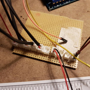
Full marks for how to post an image, but it might be nice to see the back side of the board - is it just "Vero" (stripboard)?
Some capacitors might be a good idea on a power bus - not every socket by any means as they are just close together but a few 0.1 µF and a 470 µF would be good.
Please cite these capacitive sensors - Web links - so we follow how they are supposed to operate. Please also give a photo of your "alternate" method of connection which seems to work better.
Now what is important to minimise interference, is to ensure that the power supply wires and the sensor data wires are bundled together and travel as a bundle. Lashing with nylon cord (fishing line) is a good approach.
In your photo, I see only the power wires suggesting that the data wire takes a different path, forming a large loop which can pick up or radiate interference. That is not only a problem with interference, but is also causing the problem you describe with visual mess and difficulty of maintenance.
This is the setup that works, using the same PSU (bottom left of pic), going into the same 2596 stepdown converter, outputting 5V onto 2 little copper bus bars (1mm bare copper wire) then pair of croc clips going straight to each device.
I've tested the plug board, all are at 5.02V, no shorts.
Yes the sensor lead is long and wasn't bundled with the power wires, but isn't bundled with the croc-clip setup either.
How are you reading the output from the sensors? The peak detector in them has an extremely high output impedance. I have no experience with it, but I've read some threads here about the effective input impedance of the analog inputs being not really high (not the measured impedance, but the impedance necessary to perform an accurate conversion)1. The high impedance also makes any wiring between the sensor and its load, very sensitive.
There is another problem. The way the sensors work, the 555 timer generates a pulse wave to excite one electrode and the other electrode output is rectified and filtered (peak detector). If the sensors are in too close proximity, the field from the exciter electrode of one sensor can be sensed by the pickup electrode of another sensor.
I'm not finished there is another potential pitfall. All the 555 oscillators operate at nearly the same frequency. Without exceptional isolation, some (or all) of the oscillators will synchronize. This can easily happen through the power supply lines. Due to the phenomenon mentioned in the last paragraph, this could change the readings because a synchronized field combining exciter fields from all the adjacent sensors, would be different than the readings when the oscillators are not synchronized. As the temperature and phase of the moon changes, oscillators could synchronize and de-synchronize randomly.
Note 1. From the 2560 data sheet - "The ADC is optimized for analog signals with an output impedance of approximately 10k ohms or less. If such a sourceis used, the sampling time will be negligible. If a source with higher impedance is used, the sampling time willdepend on how long time the source needs to charge the S/H capacitor, which can vary widely. The user is recom-mended to only use low impedant sources with slowly varying signals, since this minimizes the required chargetransfer to the S/H capacitor."