Help Needed: Power Factor Measurement Circuit with Arduino (ACS712 & Zero Crossing Detector)
Hello everyone,
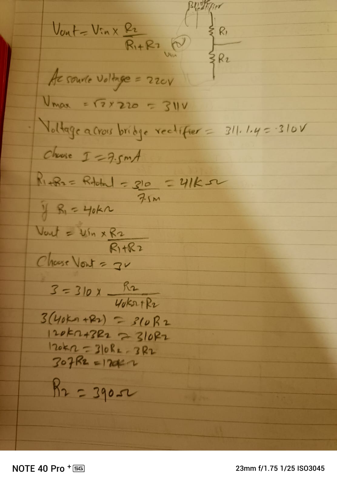
I am working on a power factor measurement project using an Arduino, and I need help debugging my circuit and code. The setup includes: 220v voltage divider vout=3v , R1=40K,R2=390 take I=1.75mA
AC Source Voltage=220V
V
max
=√2×220=311V
Voltage across the bridge rectifier= 311-1.4= 310V
Choose I= 7.5mA
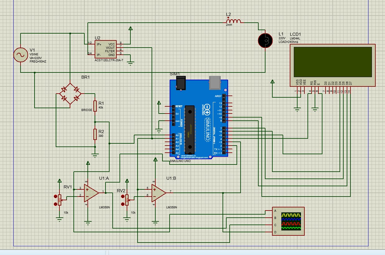
Voltage sensing via a voltage divider. Current sensing using an ACS712 sensor (20A, 100mV/A). Zero Crossing Detector using an LM358 comparator. Display on a 20x4 LCD.
i shared the circuit design
can you create thec code of this circuit design please and share
Please tell me you have not connected that circuit to mains.
What is your level of electrical and electronic knowledge? The whole thing is live and if any part of it is connected to earth, for example by plugging in a USB cable from your PC, it will go BANG! , as will your PC.
iam a 3 year student of electrical and elctronics engineeering
do not worry iam just using proteus to simulate
for pf calculation iam using this but i do not know much
Zero Crossing Detector
Zero crossing detector is used to detect sine wave zero
crossing from positive half cycle to negative cycle or negative
half cycle to positive half cycle. To measure time difference
between two waves is to detect zero crossing of two waves.
The 220V, AC is step down using step down voltage and a
current sensing unit is used to extract the waveforms of current.
The output of the voltage sensing circuit is proportional to the
voltage across the load and current sensing circuit is
proportional to the current through the load. These waveforms
are fed to voltage comparators constructed using operational
amplifier. It is zero crossing detector, and its output changes
during zero crossing of the voltage and current waveforms.
These outputs are fed to the controller unit which does the
further power factor calculations. Zero crossing detector using
LM358 as a comparator is shown in figure.
The circuit is "dangerous", though under fully autonomous operation, nothing should happen beyond potential electronic failure if faults occur. However, never connect it to anything else simultaneously, and of course, never connect it to a computer via USB.
To detect zero crossings, you need to monitor the signals arriving at each op-amp (operational amplifier).
For U1:A: The voltage input comes from a full-wave rectifier, so it will never have negative values. Adjust RV1 to a low enough value so that the op-amp output remains saturated most of the time and stays at zero for the shortest adjustable duration.
For U1:B: The voltage input comes from the ACS712 sensor. When it detects 0 amps, the output is Vcc/2, so adjust the negative input of U1:B via RV2 to this voltage.
Additional note: As a third-year engineering student, you should know that in real-world applications, the phase shift in zero crossings between voltage and current is not always indicative of real power factor; it’s only valid when the waveforms are fairly sinusoidal.
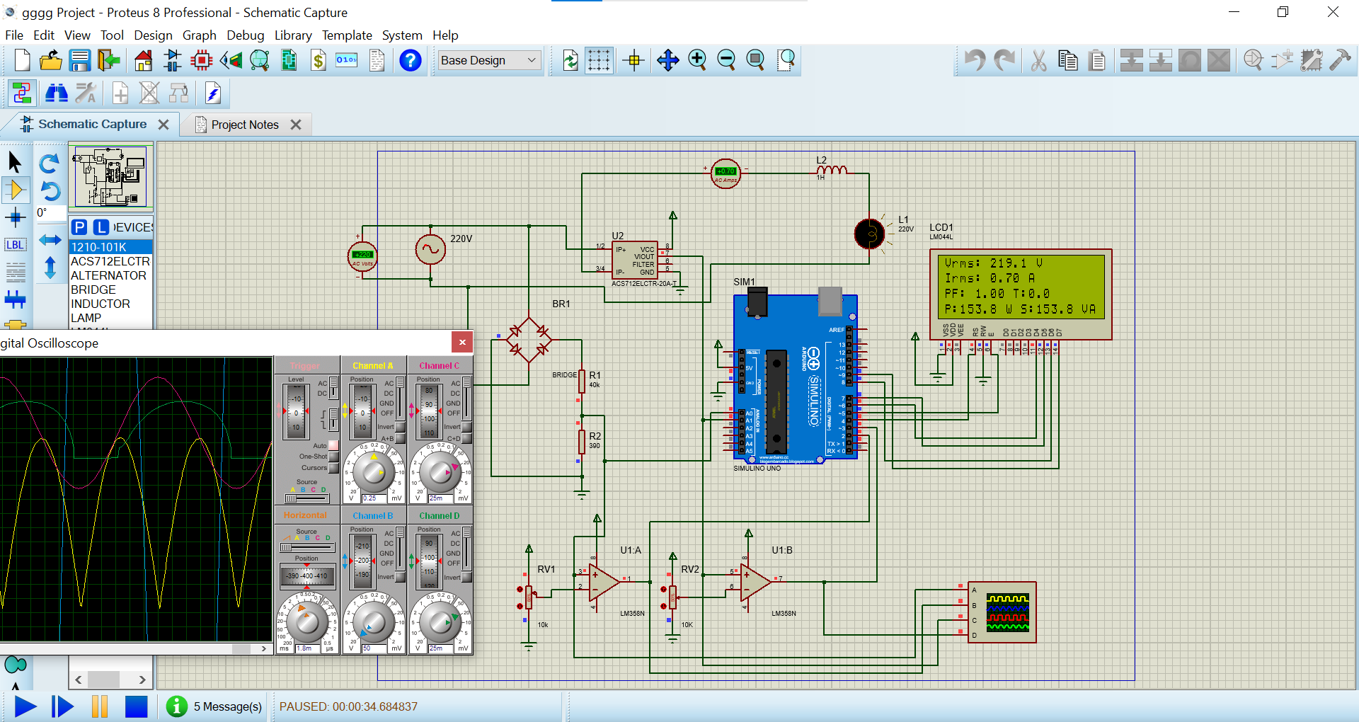
this is my circuit design and the code when i run the code i get pf=1.00 theta 0.00 always even i connect inductor 1H and lamp
i was expacting to get 0.63 when the load inductive is 1H
how can i solve this issue